Digitálne hodiny s AVR ATmega8
Experimenty s AVR Atmel ATmega8 ma priviedli k myšlienke postaviť si digitálne hodiny. Sedemsegmentových displejov sa mi doma povaľovalo dosť, tak prečo s nimi niečo neskúsiť.
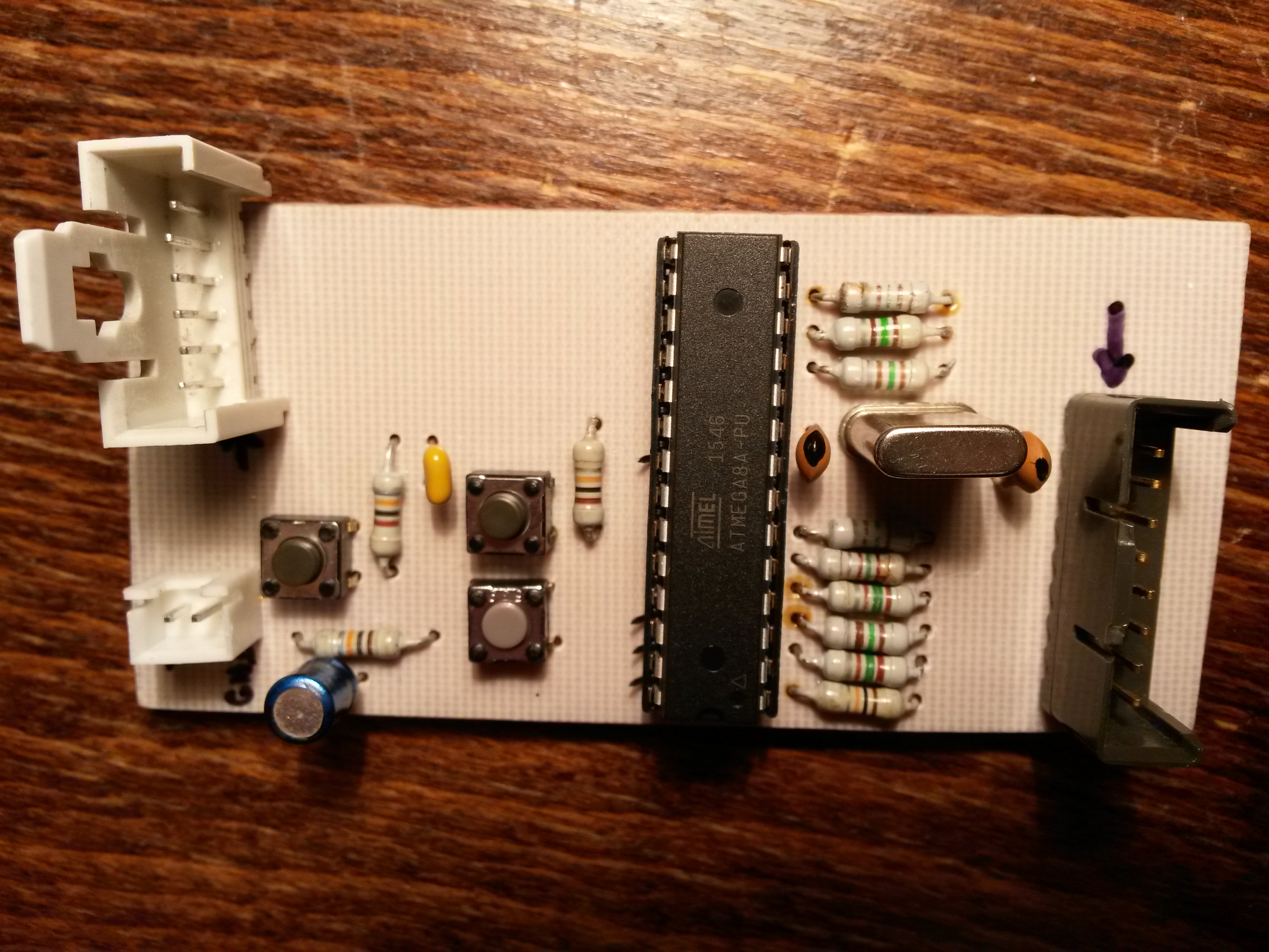
Návodov na hodiny je na internete nepreberné množstvo, len si vybrať. Narazil som na jednoduché hodiny na stránke daqq.eu a schéma i program sa mi zdali dosť jednoduché. Problém bol iba s kryštálom dosť špecifickej frekvencie, ktorý som nemal. Mal som ale kopu iných kryštálov, tak som začal študovať, či by sa nedal niektorý z nich použiť. Zistil som, že to nie je také jednoduché, že tá špecifická frekvencia má svoje opodstatnenie. Táto stránka popisuje TIMERy v AVR pre začiatočníkov a veľmi mi pomohla ich pochopiť.
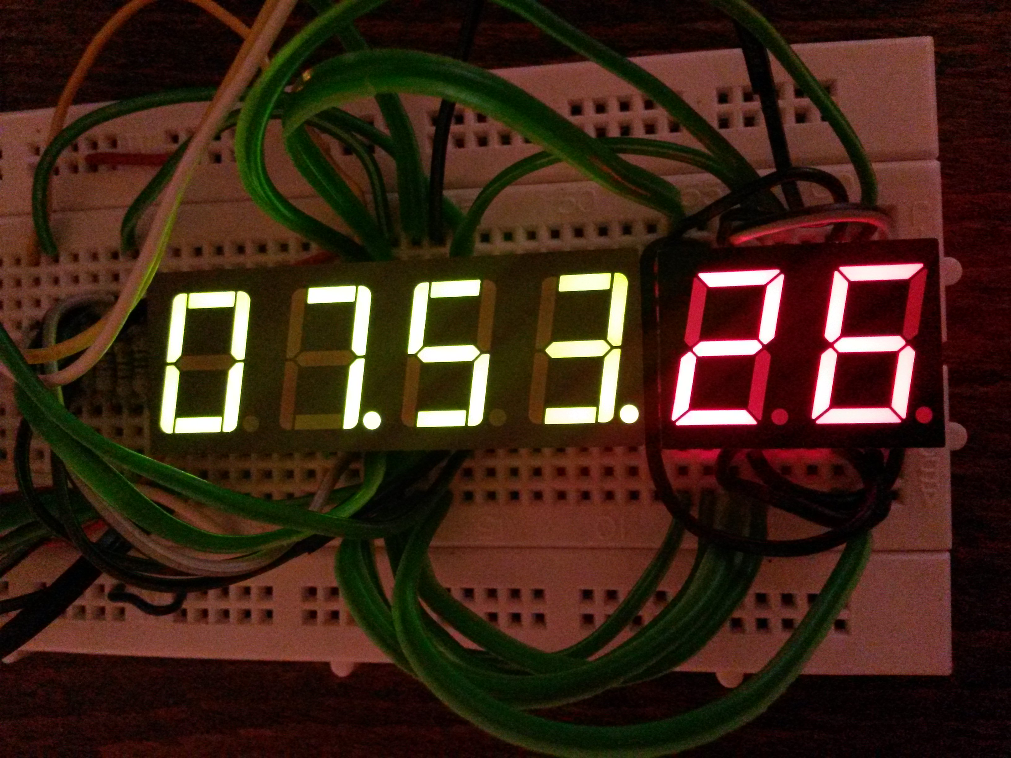
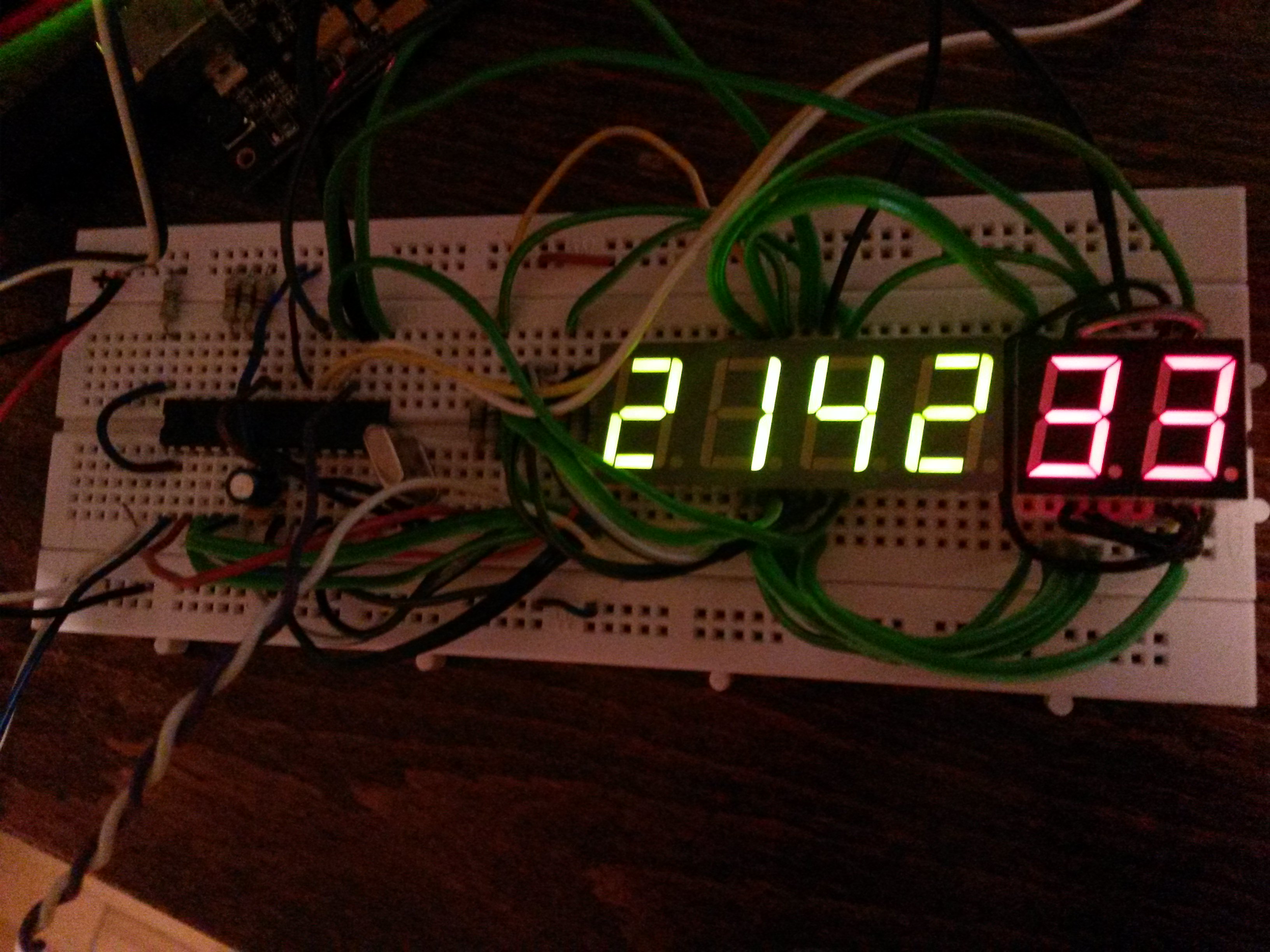
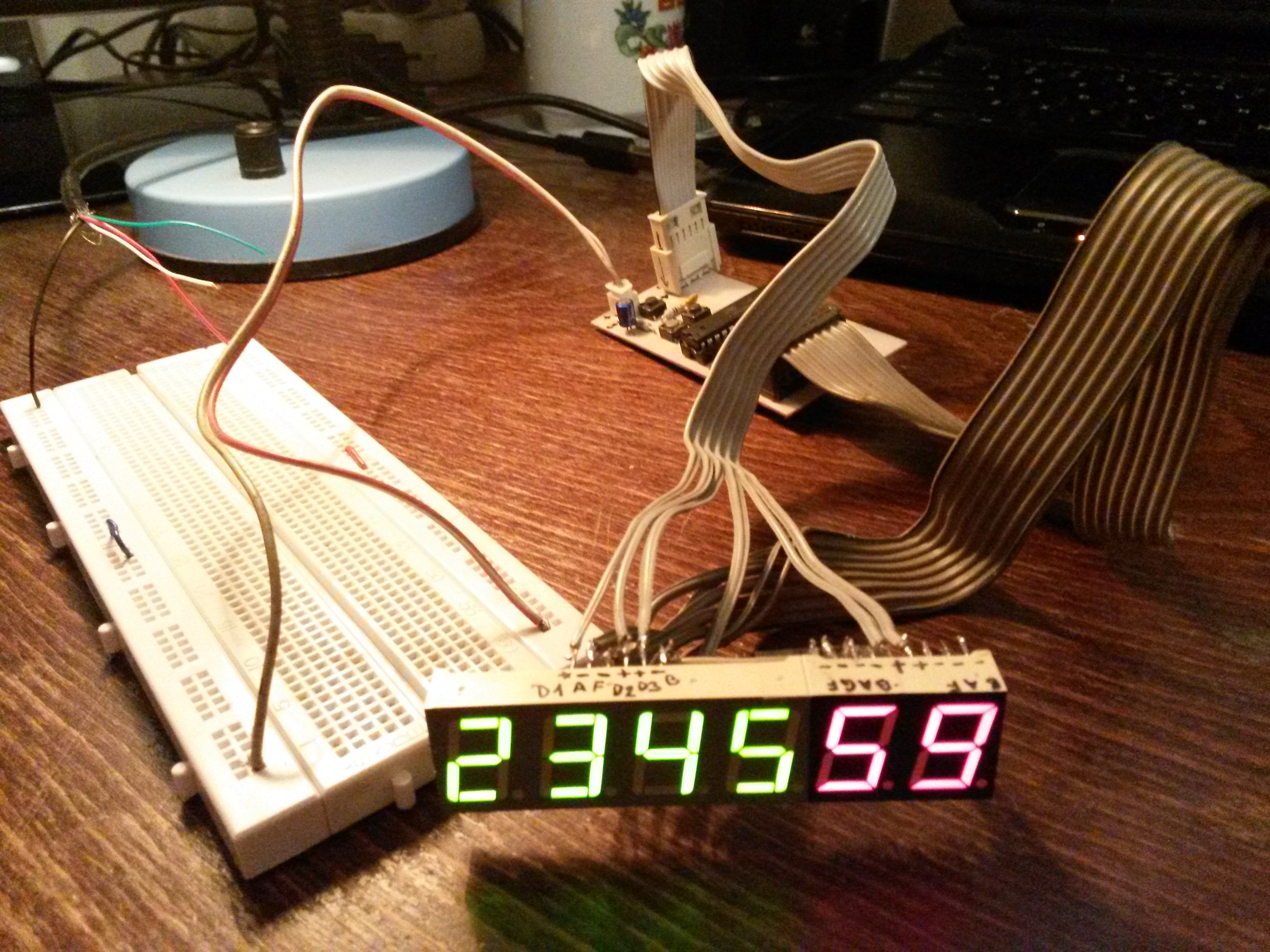
Pôvodné zapojenie som si upravil pre 6 displejov (chcel som aj sekundy), radikálne som upravil program v C, a nastavovanie hodín som prerobil tak, aby pri stlačení jedného z tlačidiel išli hodiny rýchlejšie.
Pre stručnosť, charakteristiky hodín sú:
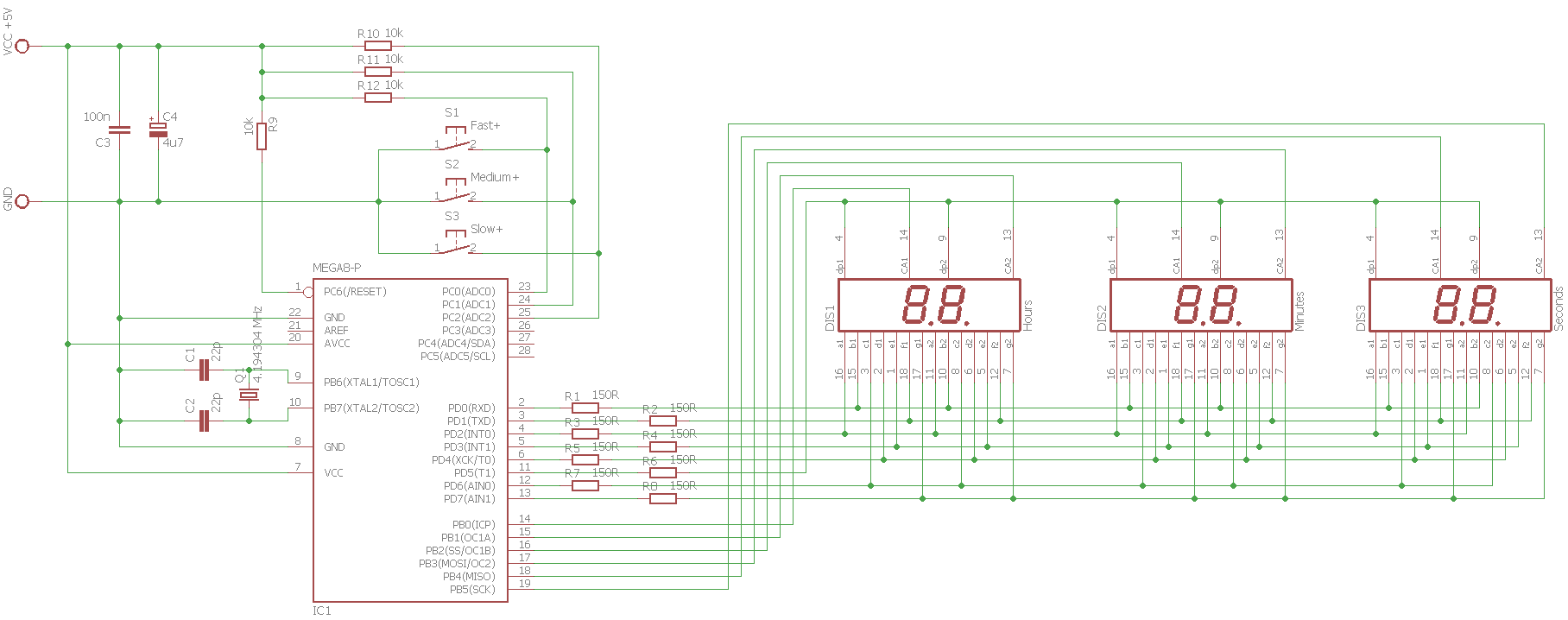
- kryštál 4,194304 MHz
- 24-hodinový formát času
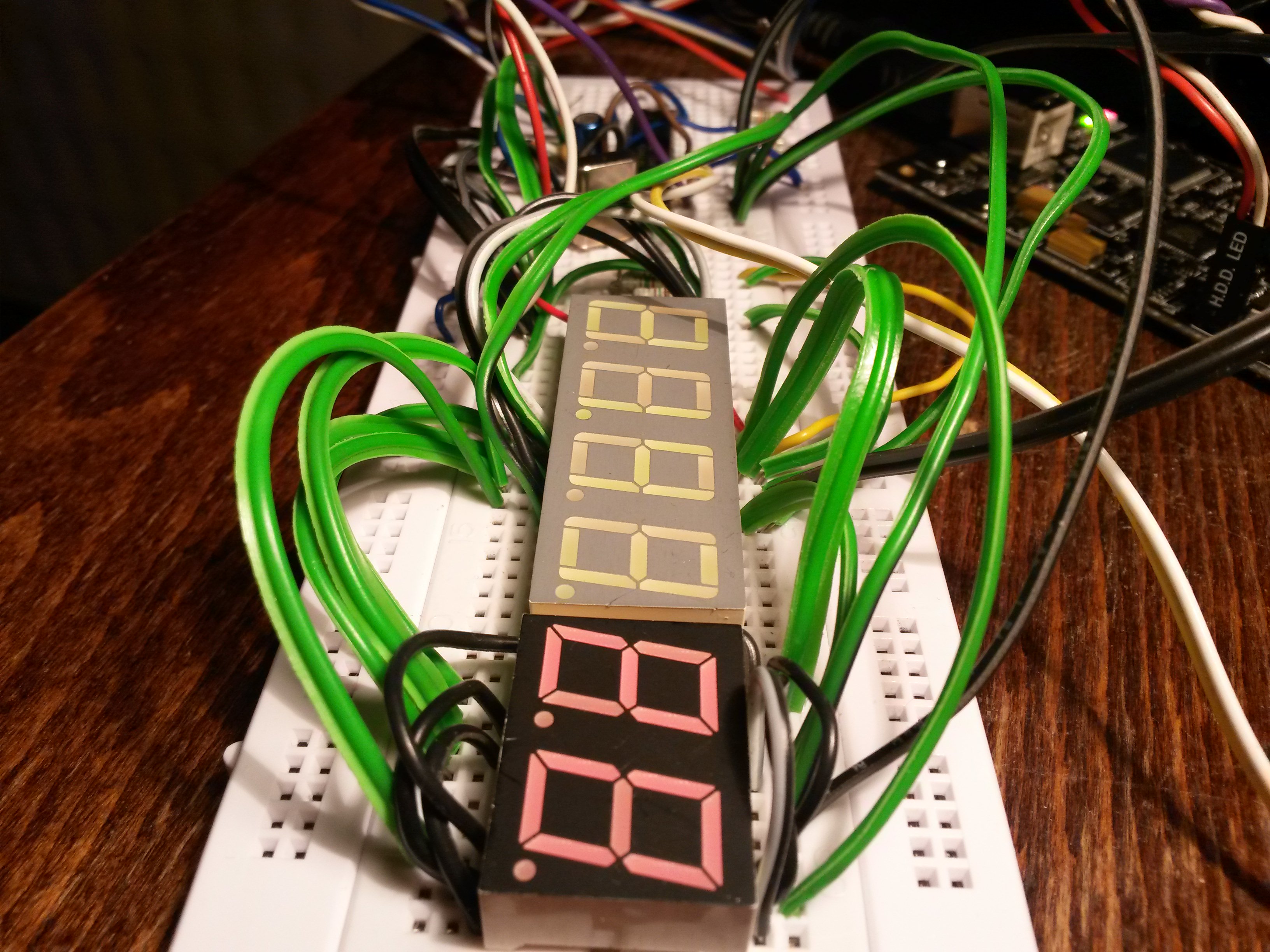
- 6 sedemsegmentových displejov s bodkami (riadené multiplexne), displeje sú so spoločnou anódou
- zobrazenie HH:MM:SS
- nastavovanie hodín troma tlačidlami, každé zrýchľuje hodiny inak
- napájanie 5V DC
Schéma zapojenia vyzerá takto:
A program s podrobnými komentármi:
#include "hw.h"
#include <avr/io.h>
#include <avr/interrupt.h>
#include<stdio.h>
// BTNx is 1 if respective button is pressed TIMER1_COMPA interrupt once per second
#define BTN0() (bit_is_clear(PINC, 0))
#define BTN1() (bit_is_clear(PINC, 1))
#define BTN2() (bit_is_clear(PINC, 2))
// default TIMER1 compare value to get
#define DEFAULT_OCR1A 16383
volatile unsigned char sec1 = 0;
volatile unsigned char sec10 = 0;
volatile unsigned char min1 = 0;
volatile unsigned char min10 = 0;
volatile unsigned char hour1 = 0;
volatile unsigned char hour10 = 0;
volatile unsigned char activeseg = 0; // indicates active display segment (used for multiplexing)
// display segments configuration
#define _s_A 2
#define _s_B 0
#define _s_C 6
#define _s_D 4
#define _s_E 3
#define _s_F 1
#define _s_G 7
#define _s_dot 5
const unsigned char segs[] =
{
_BV(_s_A) | _BV(_s_B) | _BV(_s_C) | _BV(_s_D) | _BV(_s_E) | _BV(_s_F), //0
_BV(_s_B) | _BV(_s_C), //1
_BV(_s_A) | _BV(_s_B) | _BV(_s_D) | _BV(_s_E) | _BV(_s_G), //2
_BV(_s_A) | _BV(_s_B) | _BV(_s_C) | _BV(_s_D) | _BV(_s_G), //3
_BV(_s_B) | _BV(_s_C) | _BV(_s_F) | _BV(_s_G), //4
_BV(_s_A) | _BV(_s_C) | _BV(_s_D) | _BV(_s_F) | _BV(_s_G), //5
_BV(_s_A) | _BV(_s_C) | _BV(_s_D) | _BV(_s_E) | _BV(_s_F) | _BV(_s_G), //6
_BV(_s_A) | _BV(_s_B) | _BV(_s_C), //7
_BV(_s_A) | _BV(_s_B) | _BV(_s_C) | _BV(_s_D) | _BV(_s_E) | _BV(_s_F) | _BV(_s_G),//8
_BV(_s_A) | _BV(_s_B) | _BV(_s_C) | _BV(_s_D) | _BV(_s_F) | _BV(_s_G),//9
_BV(_s_A) | _BV(_s_B) | _BV(_s_C) | _BV(_s_E) | _BV(_s_F) | _BV(_s_G), //A
_BV(_s_C) | _BV(_s_D) | _BV(_s_E) | _BV(_s_F) | _BV(_s_G), //B
_BV(_s_A) | _BV(_s_D) | _BV(_s_E) | _BV(_s_F), //C
_BV(_s_B) | _BV(_s_C) | _BV(_s_D) | _BV(_s_E) | _BV(_s_G), //D
_BV(_s_A) | _BV(_s_D) | _BV(_s_E) | _BV(_s_F) | _BV(_s_G), //E
_BV(_s_A) | _BV(_s_E) | _BV(_s_F) | _BV(_s_G) //F
};
int main(void)
{
// set all PORTB and PORTD pins as output
DDRB = 0xFF;
DDRD = 0xFF;
// show empty display at the beginning
PORTB = 0xFF;
PORTD = 0xFF;
// TIMER1 configuration
TCCR1B |= _BV(WGM12); // configure timer 1 for CTC mode
TIMSK |= _BV(OCIE1A); // enable CTC interrupt
OCR1A = DEFAULT_OCR1A; // set CTC compare value
TCCR1B |= _BV(CS12); // configure prescaler to 256 and start timer
// TIMER2 configuration
TIMSK |= _BV(TOIE2); // enable overflow interrupt
TCCR2 |= _BV(CS21); // configure prescaler to 8 and start timer
sei(); // enable global interrupts
// main loop is empty, program logic is done in interrupt vectors
for (;;)
{
}
}
// ISR of interrupt that is normally called once per second
// increases internal time information by 1 second each time
ISR(TIMER1_COMPA_vect)
{
// special handling of buttons for user configuration of time
if (OCR1A == DEFAULT_OCR1A)
{
// is some of the buttons pressed?
// if yes, decrease TIMER1 compare value to make the clock go faster accordingly
// which invokes this ISR more often than once per second
if (BTN0())
{
OCR1A = DEFAULT_OCR1A / 4096; // fastest
sec1 = 0;
sec10 = 0;
}
else if (BTN1())
{
OCR1A = DEFAULT_OCR1A / 512; // medium
sec1 = 0;
sec10 = 0;
}
else if (BTN2())
{
OCR1A = DEFAULT_OCR1A / 64; // slowest
sec1 = 0;
sec10 = 0;
}
}
else if (OCR1A != DEFAULT_OCR1A && !BTN0() && !BTN1() && !BTN2())
{
// if previously some of the buttons were pressed and now they are not
// (TIMER1 compare value is different from default)
// return TIMER11 compare value to default to make the clock go normally again
OCR1A = DEFAULT_OCR1A;
}
sec1++;
if (sec1 > 9)
{
sec10++;
sec1 = 0;
}
if (sec10 > 5)
{
min1++;
sec10 = 0;
}
if (min1 > 9)
{
min10++;
min1 = 0;
}
if (min10 > 5)
{
hour1++;
min10 = 0;
}
if (hour1 > 9)
{
hour10++;
hour1 = 0;
}
if (hour10 == 2 && hour1 == 4)
{
hour1 = 0;
hour10 = 0;
}
}
// display multiplexing is done in this ISR
// it is called often enough per second for display blinking to be invisible
ISR(TIMER2_OVF_vect)
{
if (activeseg == 5)
{
activeseg = 0;
} else {
activeseg++;
}
switch (activeseg)
{
case 0:
PORTD = ~segs[hour10];
PORTB = 1;
break;
case 1:
PORTD = ~segs[hour1];
PORTB = 2;
// blinking dot after 2nd segment
if ((sec1 & 1) == 0)
{
PORTD &= ~_BV(_s_dot);
} else {
PORTD |= _BV(_s_dot);
}
break;
case 2:
PORTD = ~segs[min10];
PORTB = 4;
break;
case 3:
PORTD = ~segs[min1];
PORTB = 8;
// blinking dot after 4th segment
if ((sec1 & 1) == 0)
{
PORTD &= ~_BV(_s_dot);
} else {
PORTD |= _BV(_s_dot);
}
break;
case 4:
PORTD = ~segs[sec10];
PORTB = 16;
break;
case 5:
PORTD = ~segs[sec1];
PORTB = 32;
break;
}
}
Pri zapisovaní programu do čipu treba zvoliť nastavenia poistiek (FUSES) takto:
- HIGH 0xD9
- LOW 0xED
- SUT_CKSEL: Ext. Crystal/Resonator Medium Freq. Start-up time: 16K CK + 4 ms (toto je súčasť nastavenia LOW fuses)
Balík na stiahnutie obsahuje program v HEX súbore, aj zdroják (solution pre Atmel Studio), schému a zoznam použitých súčiastok.
Ak sa rozhodneš postaviť tieto hodiny a budeš mať nejaký problém, ozvi sa. Poradím, ak budem vedieť.