Up konvertor pre príjem krátkovlnných staníc na PC
Na internete je za lacný peniaz dostupný USB prijímač DVB-T, DAB+ a FM rádia, ktorý nadšenci používajú na počúvanie aj iných frekvencií. Tento prijímač, založený na čipsete RTL2832 alebo R820T2 má mnoho čínskych klonov, ale všetky majú podobný frekvenčný rozsah - od cca 50 MHz, po 2 GHz. V tomto USB prijímači sa nenachádza FM ani AM tuner, demodulácia prebieha výlučne softvérovo, teda buď v programe dodávanom výrobcom, alebo v univerzálnom programe, ktorý je priam na takéto experimenty stvorený - SDR Sharp. Pekne ukáže frekvenčné spektrum o šírke približne 1 MHz, tak človek vie, čo je "vo vzduchu" a na ktoré frekvencie sa pri ladení zamerať.
Hardvérové obmedzenie týchto lacných USB prijímačov neumožňuje prijímať frekvencie krátkovlnných vysielačov, ktoré sú typicky v jednotkách MHz. Dá sa to obísť zaradením tzv. up konvertora, ktorý "zdvihne" tieto nízke frekvencie o dostatočný počet MHz, aby ich USB prijímač vedel prijať.
Tento up konvertor pridá 100 MHz k frekvenciám 0 - 30 MHz, takže v SDR Sharp-e je možné na frekvenciách 100 - 130 MHz naladiť krátkovlnné a stredovlnné vysielanie. Keďže žiadny kryštálový oscilátor nekmitá presne na 100 MHz - je to o niečo viacej, alebo menej - je vhodné to zistiť podľa výrazného "peaku" v SDR Sharp-e v okolí 100 MHz, a presnú frekvenciu zapísať ako záporné číslo do políčka Shift. To spôsobí, že človek môže spokojne ladiť na "skutočných" frekvenciách 0-30 MHz, a softvér dopočíta frekvenciu, ktorú dáva up konvertor. Ja som zadal do políčka Shift hodnotu -99 992 500, ako vidieť na videu nižšie.
V mojom prípade sa pod 2 MHz vyskytuje nevysvetliteľné rušenie, ktoré "pochoduje" v závislosti od toho, ako posúvam frekvenciu pri ladení, pričom to rušenie sa hýbe rýchlejšie, než ladím - neviem to lepšie popísať. Podstatné je, že som sa tohto rušenia nedokázal zbaviť. Závisí to pravdepodobne aj od plošného spoja - jeden človek z internetu konvertor postavil na profesionálne vyzerajúcom plošáku s SMD súčiastkami a žiadne rušenie nemal. Keď som postavil tento konvertor znova, tentokrát s použitím jeho návrhu plošného spoja, situácia sa značne zlepšila - dokázal som prijímať stanice až do 1 MHz, aj keď to "pochodujúce rušenie" tam stále bolo. Pritom som zmenšil cievky na priemer 3 mm, ucvakol súčiastkam vývody a letoval ich spôsobom SMD montáže, aby som čo najviac zamedzil vzájomnému rušeniu... tak neviem.
Zapojenie up konvertora je podľa stránky Tomasza Watorowského. Pár dôležitých vecí tam ale nepopisuje, a tak som na ne musel prísť sám.
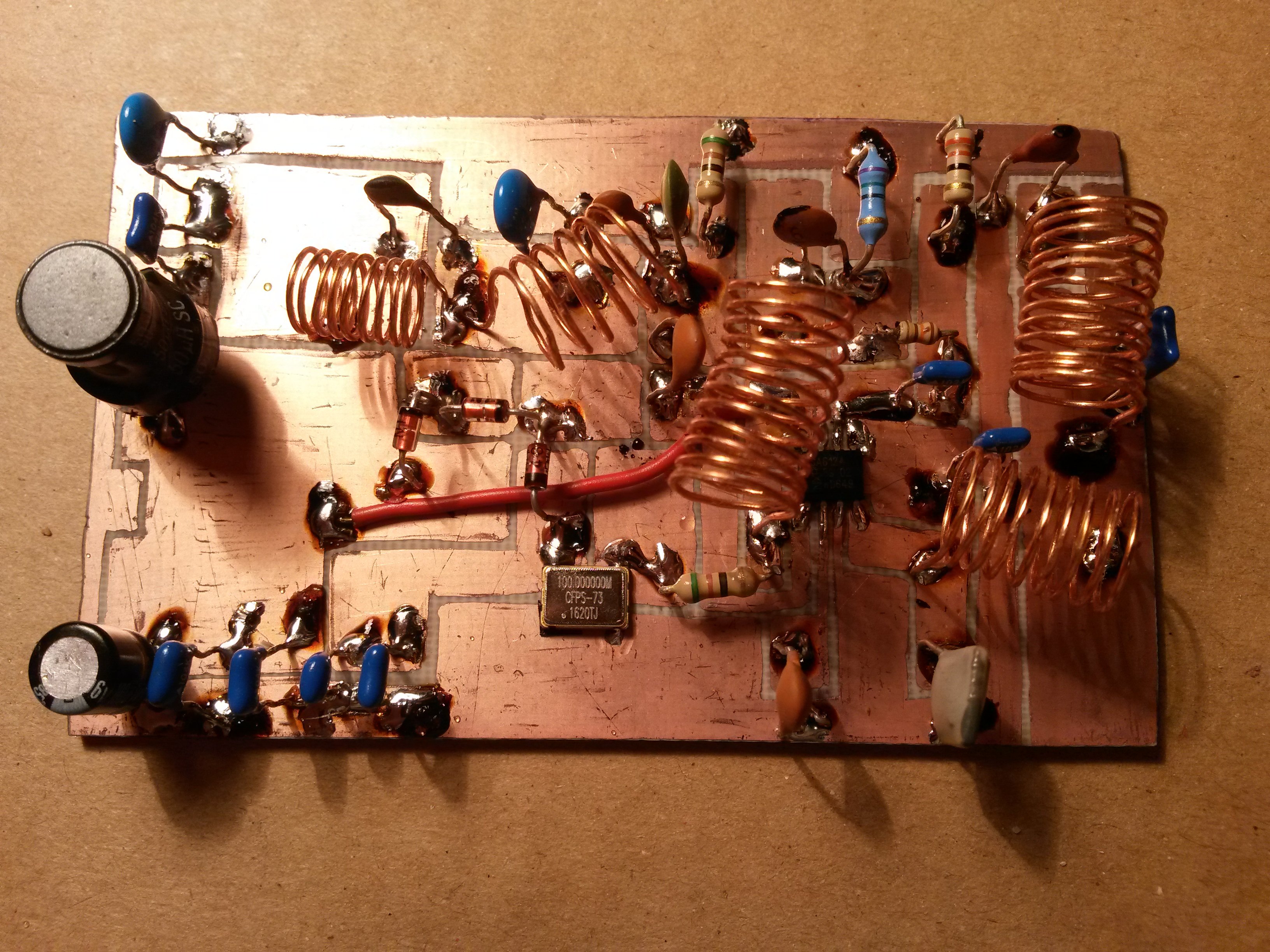
Cievky sú vzduchové, navinúť si ich môže každý sám podľa toho, aký Cu drôt a aký priemer nejakej veci kruhového prierezu má zrovna poruke (ja som navíjal na ceruzku). Na výpočet cievok potrebnej indukčnosti som použil túto českú stránku. Všetky moje cievky sú z lakovaného Cu drôtu priemeru 0,5 mm, ktorý sa dá získať napr. z rozobratého televízora, transformátora atď.
150 nH: 6 závitov, 7,4 mm priemer cievky, 11 mm dĺžka cievky
270 nH: 9 závitov, 5,5 mm priemer cievky, 8 mm dĺžka cievky
330 nH: 9 závitov, 7,4 mm priemer cievky, 12 mm dĺžka cievky
470 nH: 12 závitov, 7,4 mm priemer cievky, 15 mm dĺžka cievky
Vstupnú tlmivku o indukčnosti 56 μH, som získal z nejakého rozobratého prístroja, nenavíjal som ju.
Ku stavbe som potreboval dokúpiť v podstate len dve súčiastky, a to:
Aktualizácia 10.6.2017: Podarilo sa mi čiastočne odstrániť rušenie v pásme okolo 4 MHz, a zároveň sa mi tam objavili stanice, ktoré tam kvôli rušeniu neboli. Zabralo pridanie 47 pF kondenzátora na anténny vstup (do série s anténou). Pod 3,5 MHz je pásmo ale stále zarušené.
Posledná dôležitá vec je nastaviť v SDR Sharp-e RF Gain na 14-21 dB, inak vo frekvenčnom spektre neuvidíš nič. Tiež sa to nikde nespomína (ako keby to bola samozrejmosť), a čudoval som sa, prečo mi to asi tak nefunguje. Samozrejme sa treba prepnúť do režimu AM.
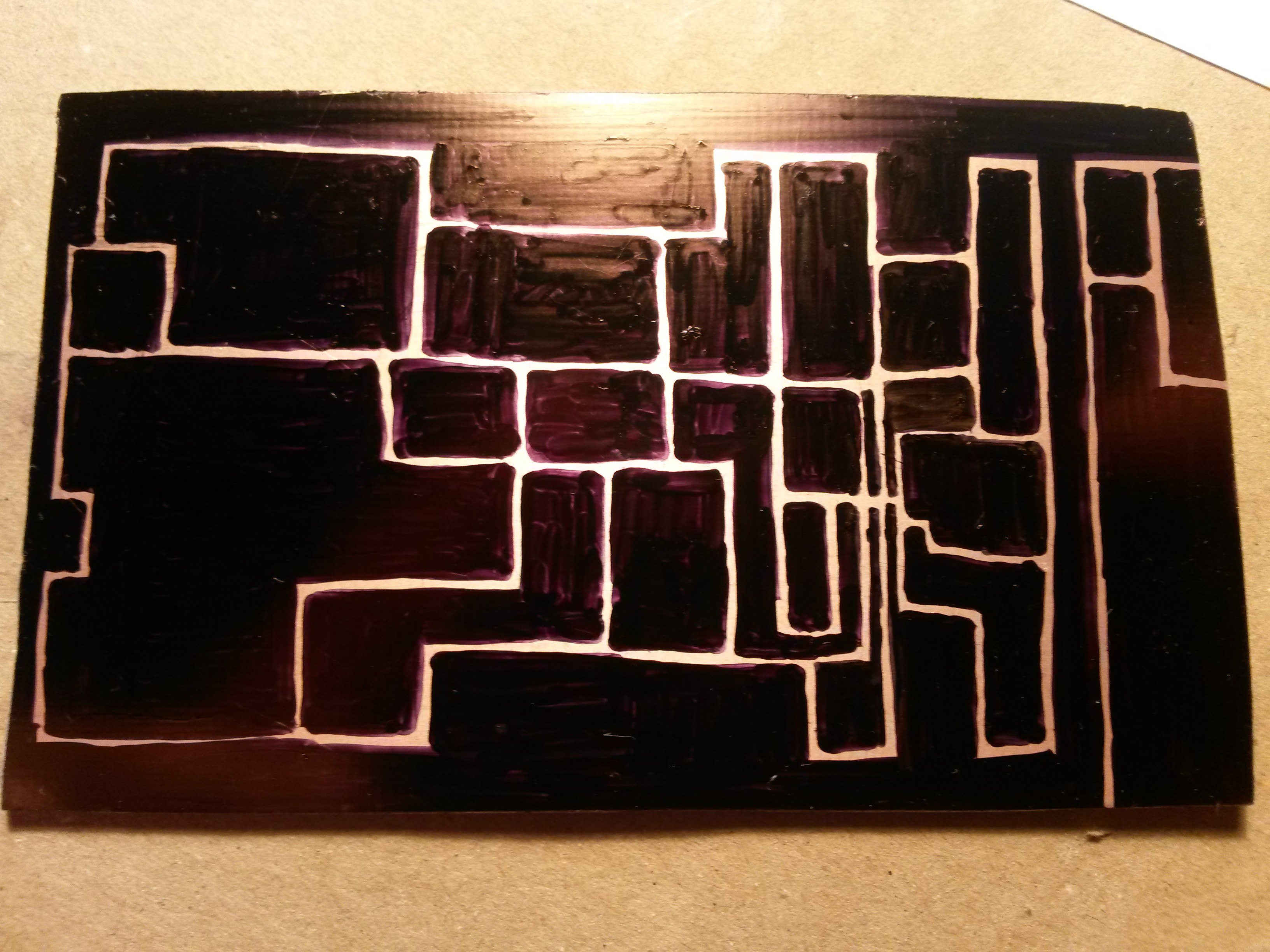
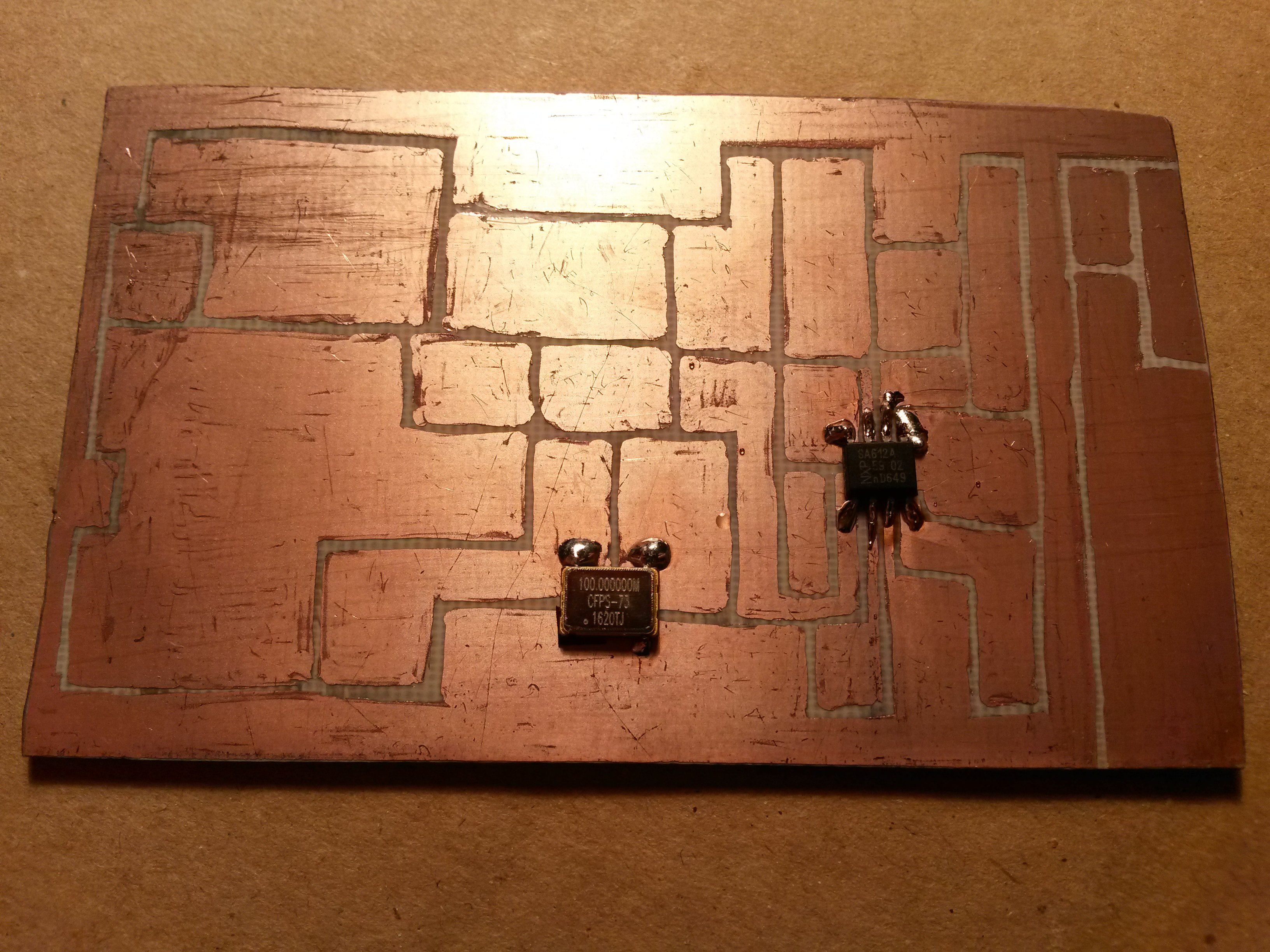
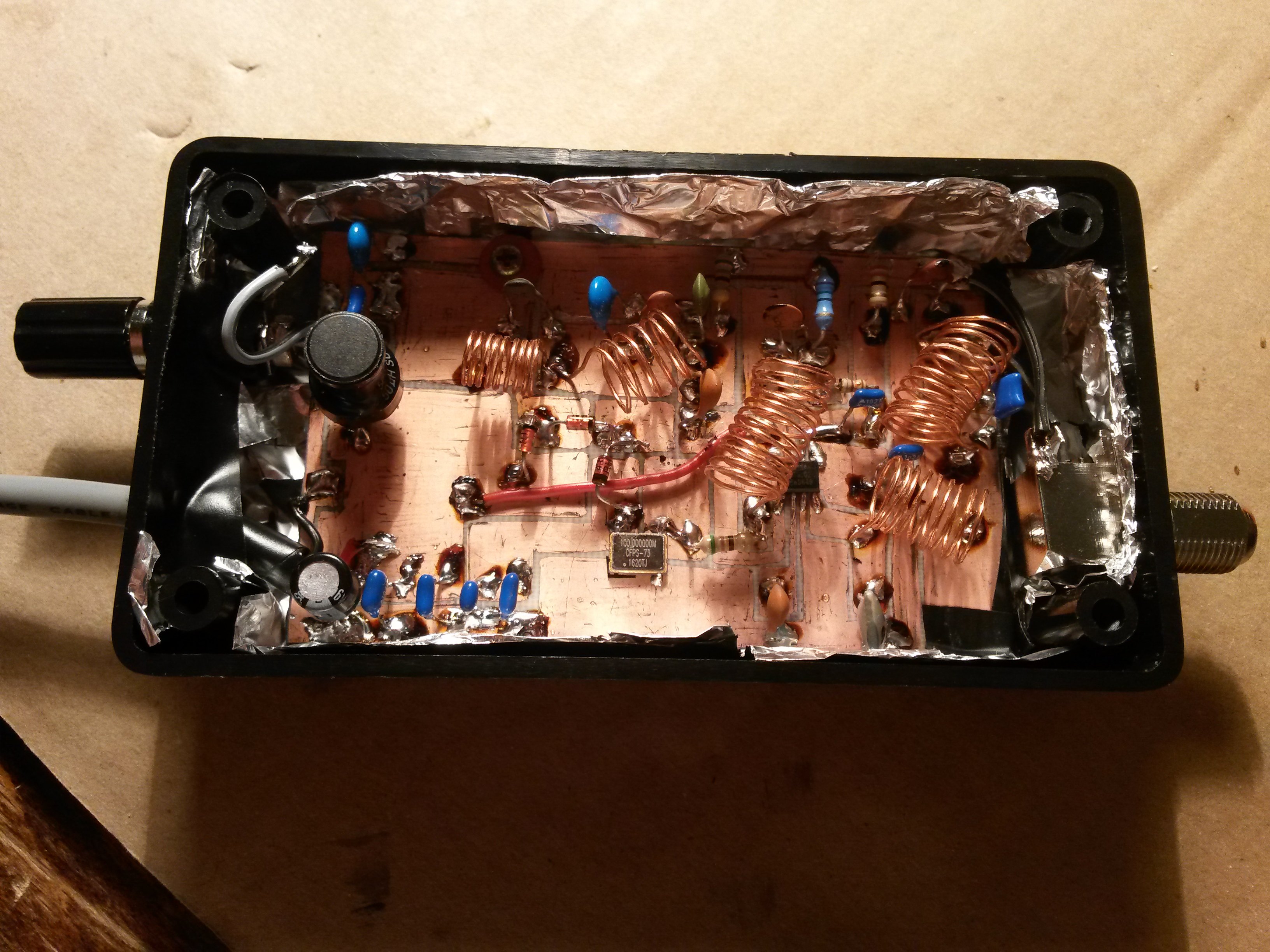
Plošný spoj som si navrhol sám. Jeho rozmery sú 5 cm x 8,5 cm a bol navrhnutý tak, aby sa zmestil do krabičky Z76. Je tam len jedna drôtová prepojka, a to z Vcc na pin 8 (napájanie) čipu SA612.
Krátkovlnné stanice sa najlepšie prijímajú po západe slnka a v noci, vtedy je najlepší signál. Tak veľa šťastia pri stavbe konvertora a veselé ladenie!
with the sma input cable in place, I connected a 1 meter long wire to the input of the circuit, but it didn't help! those multiple high peaks around 100 mhz were still there. maybe I should desolder that completely, and give it another chance. one interesting thing is that when I move the battery around the circuit at various positions, the waveforms change! I will try to assemble a clean copy of it on a breadboard at some future time when I am less busy.
thanks again
Mek
26. novembra 2019 16:40
The SMA connector is not a problem. The antenna should be just a simple wire - no coaxial, no shielded cable, nothing. Just a simple copper wire. Solder it on the input where the SMA connector is (you can leave the SMA connector soldered as well). Length of the cable should be a few meters, the more length the better, and should be placed horizontally, in highest place possible.
I'm pretty sure this will help
Mahdi
26. novembra 2019 08:52
you mean I should replace the antenna? in the figure below, the purple coaxial is input, on one end it has female sma, the other end is soldered to the board. I just bought it as a connector, I don't know the impedance of it, whether it is 50 ohm or 75 ohm. a pdf file of it is uploaded in: https://docdro.id/0eF7BqL
the shield is soldered to the pcb gnd, and the inner connector is soldered to the lead of the input capacitor, C4.
for connecting any other antenna, I used the same cable, my sdr dongle is shipped with an antenna with a magnetic base and a male sma connector; I used it. I connected the male sma coming out of the magnetic base to input female sma of my pcb, and with some alligator clip, I attached some wire in place of antenna at the magnetic base. It made almost 1 m length of coaxial cable.
Do you think that is the problem? should I disconnect the female sma connector?
thanks
Mek
25. novembra 2019 18:05
OK, that may mean the problem actually is the antenna. Is it just a wire, or a standard 50 or 75-ohm coaxial cable? I have seen people using coaxial, no wonder they didn't get anything out of it, so just asking
I know the "hack" of replacing a dll in sdrsharp folder, it didn't work well for me either. Anyway, you can get best reception in the 6 MHz and 9 MHz bands, the higher the frequency, the least you can get (because not many stations broadcast there). Also the higher bands are better propagated during day, not night. If you replace a DLL then maybe you can get down to 16 MHz or so, but it's still not enough for shortwave.
It's normal that you get FM stations around 20 MHz, I am getting them as well. I consider it a bug somewhere in the RTL-SDR design
Mahdi
24. novembra 2019 23:34
now I can say that the problem is not the antenna! because even without any antenna, just sma connector is left unconnected to anything, the same peaks and noises are present everywhere.
In the future days I will try to make a new copy, as I said in my previous comment, to see whether it has the same problem.
by the way, there is one experimental method by Oliver Jowett for rtl sdr HF reception, it is a single dll file to replace in the sdr sharp folder. even with that, I am still receiving FM stations! with that software modification I can tune to above 15 Mhz, but there are just some FM stations there! a single station appeared on 16 Mhz, and at the same time, on 90 Mhz! I dont know why.
any way, thanks for your support and help
If I come up with any solution, I will let you know.
Mek
24. novembra 2019 22:19
Try just a long wire and connect it directly in place of the "SMA" input as on the schematic. The stock antenna that came with the dongle will not work, it's just not meant for short wave.
About the overloading - I only have read it somewhere, that if there is a strong signal somewhere, mirrors of it can appear in various places around the spectrum. I also saw it when my brother used his PMR to broadcast, the transmission was there in various frequencies, not just the only one. May be the same situation here. But I don't think it's important.
You can connect your shielding to GND, it's OK. I just didn't use a traditional SMA connector so there was no shielding to connect, that's all
I don't know about the other circuit you posted link to, it may work as well. I have used NE612 also in other projects, and it worked without any filters, but it is commonly known that the NE612 / SA612 is easily overloaded by strong signals and then nothing usable comes out of it, so I ended up using some simple filter as well in my other projects, but some other, older projects are without filters and perform just fine. I guess the filters in the up converter are there only to suppress regular FM stations (but they are still there, only weaker). Try the other circuit and see if that one works. Otherwise I don't know why this one doesn't work for you
Mahdi
24. novembra 2019 22:00
yes, the two TO92 packages are 78l05 for sa602 and lf33 for oscillator
currently in my country it's night, and with conventional radios I can receive short wave now.
for the antenna I have tested possible configurations, the same telescopic antenna shipped with my sdr dongle, with various lengths of it extended. I have also tried connecting a long wire inside room to that antenna when it is in the shortest length. I also connected some wire to an aluminium window pane, and from that again to the antenna. they all make the same result.
why my sdr is overloaded?? what are the possible causes?
in your uploaded file above, you mentioned that do not connected shield of input wire to the circuit gnd, but I have it connected to gnd. can it be the cause?
I have another sa602 and 100 Mhz oscillator, and the pdf below has made an up-converter without any input or output filters, or impedance matching. maybe I should give it a try with my another sa602. It has just 3 capacitors to the inputs of ne602, and a voltage divider at the output of oscillator.
http://www.davegardner.org/Ham/PDF/EasySDR.pdf
Mek
24. novembra 2019 21:27
If you have many peaks, that may mean the SDR is getting overloaded, and those peaks are only some false peaks, not really present... otherwise I don't know how to explain them.
Your power source is a 9V battery, but the circuit should be powered by 5V. I can see you are having a TO92 case in your circuit, is this a 78L05?
Try tuning around 6 MHz and around 9 MHz, those are most busy on short waves. Also, what is your antenna?
Another important note - try tuning in the evening and at night, when short waves propagation is best.
Mahdi
24. novembra 2019 21:17
Many thanks, I really appreciate your kind reception in accepting my request and answering my questions
I've played with the gain, it has some effects, but still no reception
I think there is something wrong with my circuit, there are actually many sharp peaks around 100 Mhz! not one. Some screenshots are given:
https://postimg.cc/Sn4C2drr
https://postimg.cc/1gj8Hrpb
https://postimg.cc/xJNcFN58
https://postimg.cc/K4L1PL4s
https://postimg.cc/4HCmC425
https://postimg.cc/vxWDGRpd
https://postimg.cc/dLYL41yQ
I don't know whats wrong with it. my circuit is assembled on a perfboard, all components except sa602 are through hole, capacitors are multi-layer, inductors are fixed type inductors like resistors, and it's powered by a 9 V battery. for L4, which is 470 nh, I used two 100 nh and one 270 nh in series. some pictures of it are shown in the links below. the black wire sma is output, the purple sma is input.
https://postimg.cc/jwZ0YMjS
https://postimg.cc/G926sJ2v
https://postimg.cc/rRs6V5dC
https://postimg.cc/jWtFqymw
one interesintg thing about it is that when I move the 9 V battery around, signals change! not much, but there are some changes happening
somewhere else I read that L4 and C14 are there to suppress crystall oscillations at 100 Mhz, but in my circuit there are many noises around 100 Mhz. I dont know what to do else with it. do you have any suggestions for me?
thanks
Mek
24. novembra 2019 15:24
Hi, Mahdi,
make sure you have RF Gain in your SdrSharp or any other program you may be using, set to some higher level, from 20 to 40 dB, otherwise you get nothing.
It's good there is a sharp peak at 100 Mhz, that means the oscillator is working. The peak should also disappear when you disconnect the upconverter from power.
Otherwise, I would prefer communicating using these comments under the article, because other people may find them useful as well. Good luck troubleshooting.
Mahdi
24. novembra 2019 14:01
Hi, I am Mahdi
I just build this up-converter, but mine doesn't work at all, there are only some sharp peaks around 100 Mhz, some FM stations, and the rest is all noise, and I am getting mad with it
I was searching through the net and I arrived at your page
Is there any chance I can get in contact with you, maybe by email, and get some help on trouble shooting my converter?
thanks

")
