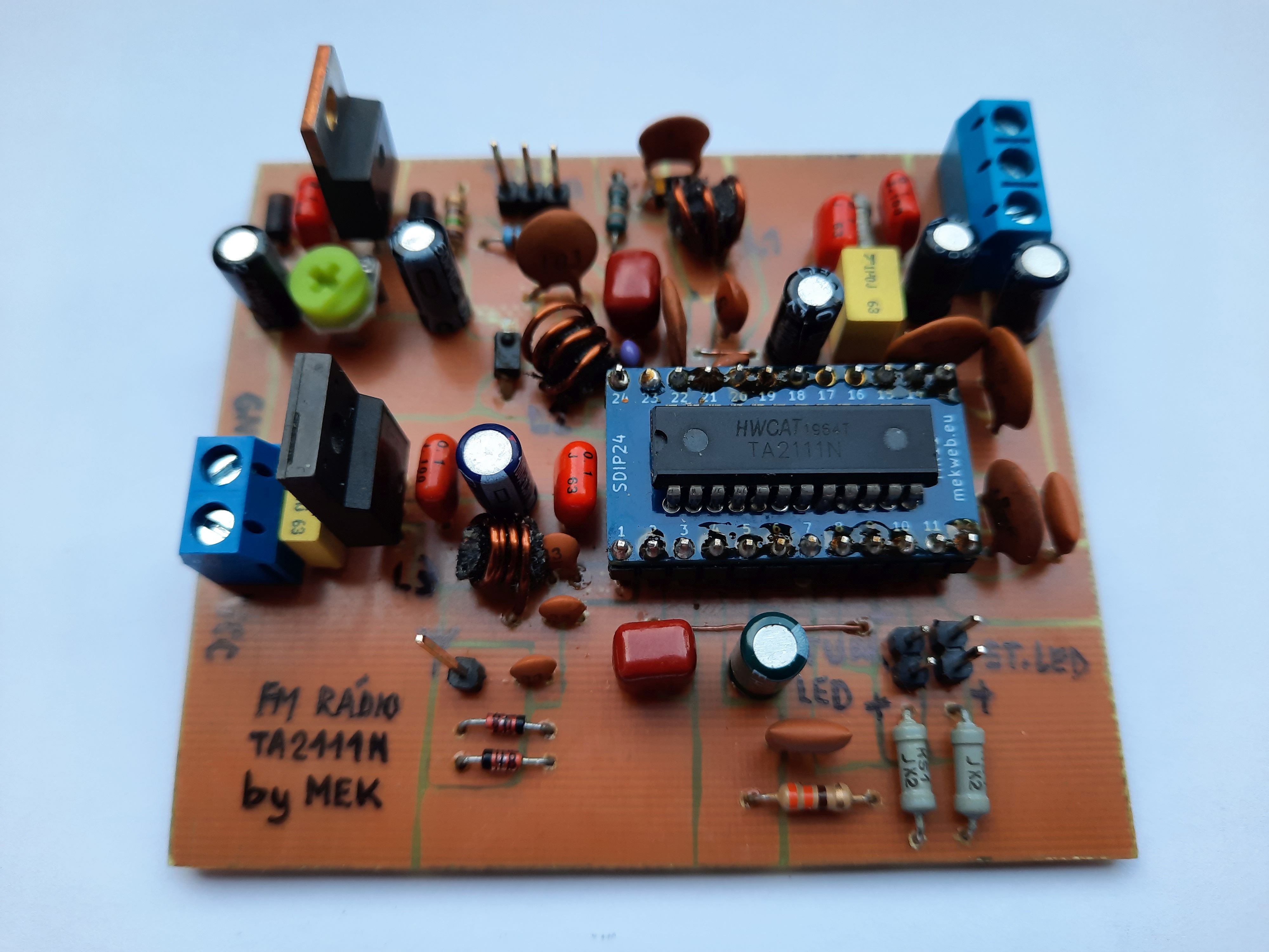
FM radio with TA2111N
I saved a radio-clock from going to waste. It had damaged enclosure so nobody would want to use it anymore, but the electronics inside was still OK. The PCB had circuits for both the clock and AM and FM radio, I just wanted the FM radio. So I desoldered the parts and designed my own PCB according to the datasheet of TA2111N.
Parameters:
- frequency range: FM 87.5 - 108 MHz
- power supply: 15 - 28 V, ca. 30 mA
- output: AF stereo
- tuning: by 10k potentiometer
- LED indication: tuned and stereo
- PCB dimensions: 8 x 7 cm
A tuning capacitor was used in the original circuit, but that is a problem when you want to re-use the circuit in your own project. Because it is tailor-made for the original enclosure, you have to think about the placement of tuning knob, solve complicated gearing, drill precisely, that's a big hassle. It's better to replace the tuning capacitor with varicaps and then use a potentiometer (multiturn for best experience), which can have longer leads and thus be placed anywhere on the panel. And that is why I used varicaps in my project, more precisely KB109G (those with yellow strip), because I got many of them from old Tesla CRT TVs. Another advantage of varicap tuning is the possibility to indicate tuning digitally - just by tuning voltage measurement and indication for example in series of LEDs - LM3914N and similar come to the rescue.
In the original circuit, apart from the tuning capacitor (that changes its capacitance according to knob position), there are also two helper tuning capacitors with low capacitance, and their purpose is fine-tuning of circuits on pins 21 and 23 of TA2111N. I measured these and replaced them with fixed capacitors. Parallel inductors are re-used from the original circuit. The main tuning capacitor is replaced by a varicap and fixed capacitor in series. Tuning voltage is applied to both varicaps, which changes their capacitance and tunes the receiver.
For completeness, the original tuning capacitor had these capacitance ranges:
- pin 21: from 12 to 33 pF
- pin 23: from 7.4 to 28 pF
... and so the chosen varicap was enough, with change of capacitance between 0 - 21 pF.
Varicap tuning also has a disadvantage - that it needs a higher voltage for the varicaps (typically up to 30 V if you want to use the complete capacitance range). In my circuit, tuning voltage of 4.5 - 12.5 V is sufficient. To mitigate any noise from eventual step-up controller, I chose supply voltage of the whole circuit to be 15 - 28 V. From this voltage, LM317 creates a precise maximum tuning voltage of 12.5 V and LM7805 creates 5 V for the rest of the circuit.
Integrated circuit TA2111N is not made in standard DIP package, only in the smaller SDIP package with lower pin pitch. I mounted it on an adapter PCB that I designed and had made in the past. It allowed me to experiment on a breadboard (yes, it worked despite much of the circuit being HF). But the PCB design allows for both.
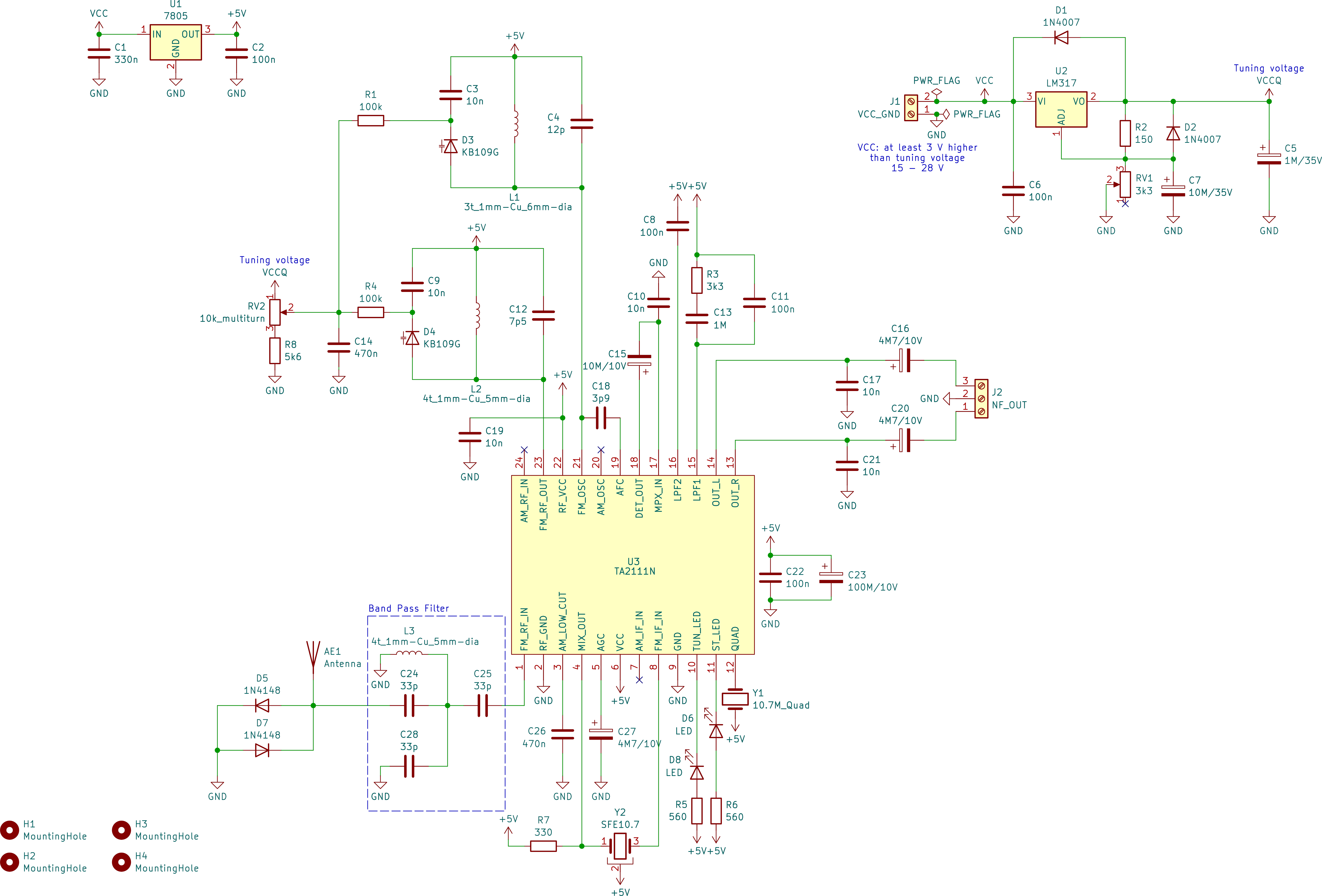
The schematics
Click to enlarge.
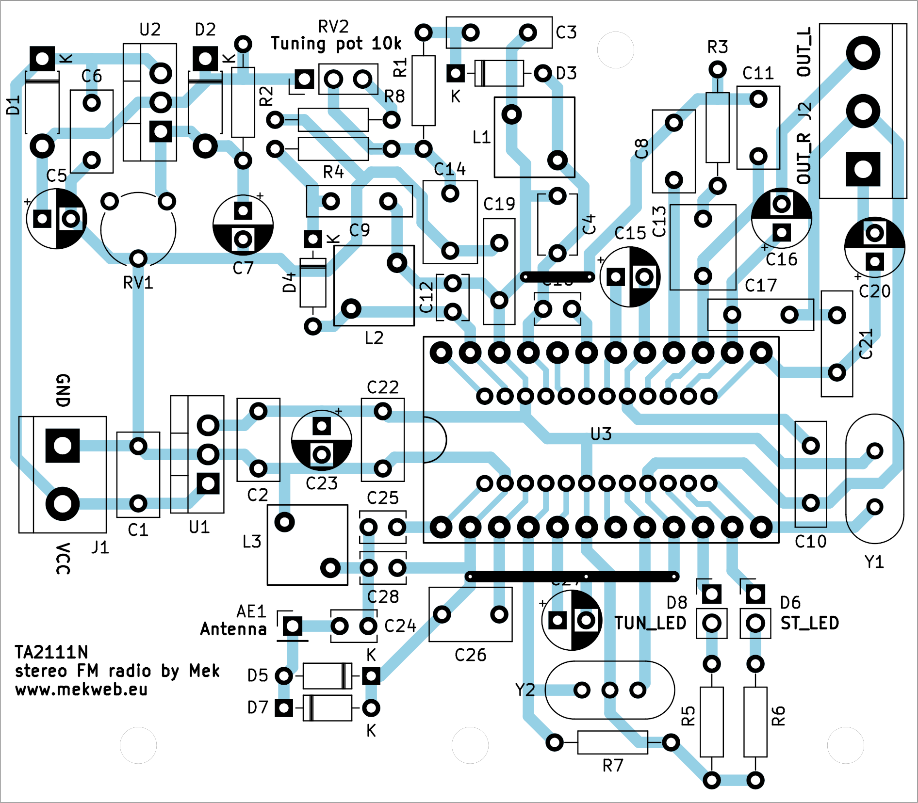
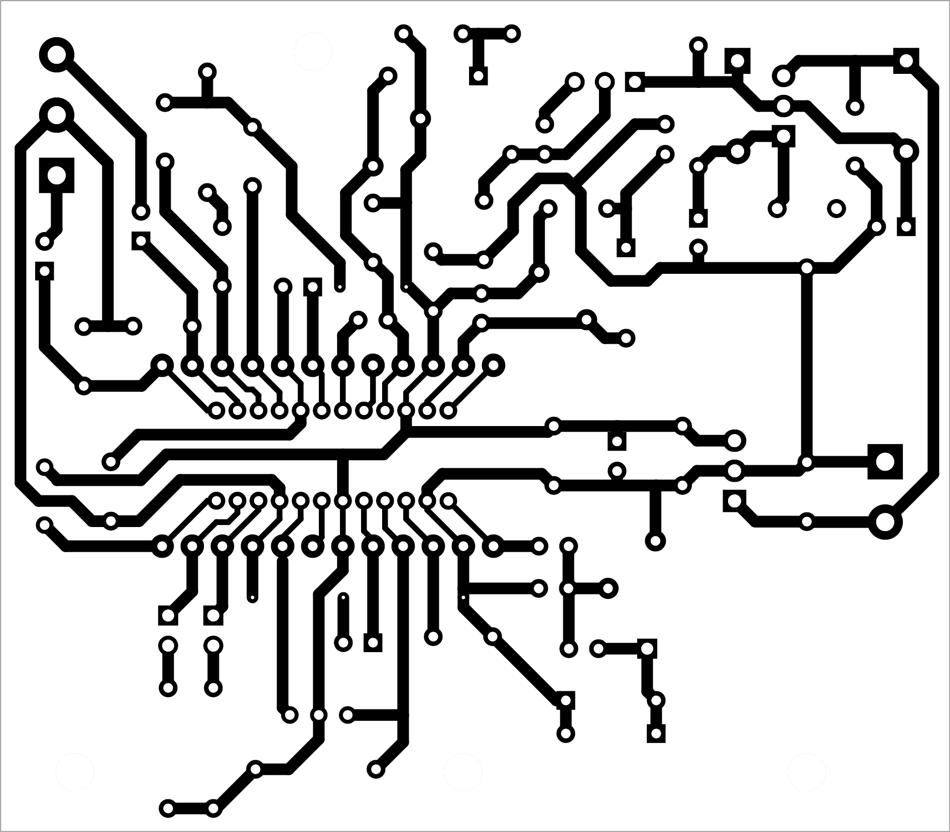
The PCB
Dimensions: 8 x 7 cm. Bottom-layer traces are in color, top-layer traces are in black. Click to enlarge.
Parts list
| AE1 | pin header 1x01, raster 2.54 mm |
| C1 | 330n |
| C2, C6, C8, C11, C22 | 100n |
| C3, C9, C10, C17, C19, C21 | 10n |
| C4 | 12p |
| C5 | 1M/35V |
| C7 | 10M/35V |
| C12 | 7p5 |
| C13 | 1M |
| C14, C26 | 470n |
| C15 | 10M/10V |
| C16, C20, C27 | 4M7/10V |
| C18 | 3p9 |
| C23 | 100M/10V |
| C24, C25, C28 | 33p |
| D1, D2 | 1N4007 |
| D3, D4 | KB109G |
| D5, D7 | 1N4148 |
| D6, D8 | pin header 1x02, raster 2.54 mm + LED |
| J1 | screw terminal 1x02, raster 5 mm |
| J2 | screw terminal 1x03, raster 5 mm |
| L1 | air coil, 3 turns 1 mm Cu wire, inner diameter 6 mm |
| L2, L3 | air coil, 4 turns 1 mm Cu wire, inner diameter 5 mm |
| R1, R4 | 100k |
| R2 | 150 |
| R3 | 3k3 |
| R5, R6 | 560 |
| R7 | 330 |
| R8 | 5k6 |
| RV1 | potentiometer for PCB, 3k3 |
| RV2 | pin header 1x03, raster 2.54 mm + multiturn potentiometer for panel, 10k |
| U1 | 7805 (TO220) |
| U2 | LM317 (TO220) |
| U3 | TA2111N |
| Y1 | 10.7 MHz quad detector |
| Y2 | 10.7 MHz ceramic filter |
Construction process
I recommend to place all components except TA2111N first, and verify that the voltage on pins 6 and 22 of TA2111N is 5 V (measured against pins 2 and 9), and no other pin has a voltage higher than 5 V. After placing the IC, make sure there are no accidental bridges between adjacent pins.
Then, measure the voltage on cathodes on the varicaps and set it to 12.5 V using the RV1 trimmer. This voltage determines the maximum tuning voltage for varicaps, when they have the lowest capacitance (corresponds to 108 MHz). For the sake of completeness - the lower end FM range 87.5 MHz is given by R8 (so that the minimum tuning voltage is 4.5 V). If something is not right, FM range can be fine-tuned using these components.
When everything is OK, you should hear FM noise after turning it on. Tune to the lowest frequency where you expect a station (or help yourself with an FM generator or FM transmitter where for example 87.5 MHz can be set). Widen and shorten the oscillator inductor L1, until you hear the expected station. Then, tune to some station near the middle of the FM range and play with the L2 and L3 inductors as well, until reception quality is best. How the final coils can look, is displayed at the bottom of this page. The inductors have the following function:
- L1: oscillator - determines where exactly in the varicap tuning range will the FM range be (87.5 - 108 MHz). We want to have it in rage of 4.5 - 12.5 V - it certainly could be higher, but then unnecessarily high voltage would be needed for the varicaps. My experiments showed that the receiver stops working under 4.5 V, maybe the oscillator stops then.
- L2: part of LC band-pass filter, that filters out other frequencies than the one that the receiver is currently tuned on.
- L3: part of antenna band-pass filter. It can be omitted (by connecting the antenna directly to pin 1 of TA2111N), but that induces a risk of unwanted signals not related to FM range entering the receiver and causing noise.
Conclusion
It's nice to re-use parts that would end up in the trash, make them work again and serve for more years.
However, after finishing the project, I found two disadvantages that I don't know the reason of:
- "tuned" LED indication is always on
- there are many "ghost" stations - that are received on frequencies they don't broadcast on. What's worse, often they overlap each other and can be heard two or three at the same time. It does not happen in the whole FM range, but is dependent on the inductance of L2, unfortunately it cannot be fine-tuned to not have these problems in the whole FM range. Perhaps that is a disadvantage of these cheap FM receiver chips, because it also happens on industry-made products, such as on the radio we have at work. I don't think it can be fixed, but normal local FM stations can be listened to without problems anyway.