Tuning indicator with 4x LM3914N
I built a complicated FM radio that was published in a Czech magazine in 1998, with parts from that era and hand-wound inductors, just to see if I could make it - and it turned out that I could :)
But how to indicate the tuned frequency? In the old times, it was indicated by a thin rope with plastic or metal indicator mounted to it, that moved on the frequency scale. That required a lot of planning and careful design and drilling to make it accurate, which I do not like at all to do myself. We have a better parts foundation today, so I used some famous LM3914N integrated circuits - these are used for bar/dot display in a series of LEDs. They can even be chained to get a longer (and more precise) display. Perfect for frequency indication in an FM receiver, where tuning is done by changing voltage on varicaps - and these integrated circuits indicate voltage on the LEDs. So, 40 LEDs should suffice for relatively precise FM tuning indication.
How to get the chaining working, was quite a mystery, because most articles on the web deal with only one IC. And the datasheet is a bit complicated, not everything is explained, schematics are only partial, and it must be read slowly and with understanding, one simply cannot get the information needed quickly.
That's why I publish my circuit here - perhaps it helps someone else. Plus, my observations:
- pins REFOUT and REFADJ are connected to the internal voltage reference. It works similar to LM317 - the REFOUT voltage is set by two resistors. The first one (680 ohms) serves also to denote the LED current. When you have R1 determined, you can calculate R2 using the formula from the datasheet (or use one of the internet calculators) to set REFOUT voltage. I used a potentiometer, because REFOUT is used to denote the upper voltage for indication - that must be set precisely.
- REFOUT voltage is used to tell the IC, which voltage range it should indicate. Theoreticaly, supply voltage could be used directly, but its eventual fluctuations would cause subtle changes in the indicated range, that's why the IC has a voltage reference built in.
- pins RLO and RHI must be connected to voltage levels that denote the lower and upper voltage level for indication. One can connect RLO to GND for indication from zero. I used potentiometers for both, because the tuning voltage of my FM radio doesn't start at zero, but around 1.65 V.
- when ICs are chained:
- the upper level (RHI) also becomes the lower level (RLO) for the next IC
- MODE pin of an IC must be connected to LED1 of the next IC
- the first LED of each IC must be shunted with 10k resistor, otherwise that LED was slightly on when any of the next ICs was active
- LED9 of each IC must be connected to VCC via a 20k resistor (as per the datasheet)
- RLO voltage must be set a bit less than expected, because all LEDs are off when voltage is in the lowest range
- the supply voltage of the IC can be up to 25 V, mine was 18.5 V
- the input (indicated) voltage can be up to 35 V
Construction process
At first, set REFOUT (and the upper voltage level) for the first IC by RV5. Then, set the lower voltage level by RV3. And at last, set upper levels of each other IC (and thus, also the lower levels of the next IC) using the other potentiometers. When adjusting voltages by the potentiometers, measure voltage on RHI and RLO pins of the specific IC.
Example: I needed to indicate FM tuning voltage in the range of 1.65 - 14.3 V. I divided it to 4 equal sub-ranges for each IC, to indicate voltage levels:
- 1.65 V - 4.81 V
- 4.81 V - 7.97 V
- 7.97 V - 11.13 V
- 11.13 V - 14.3 V
The schematics
Click to enlarge.
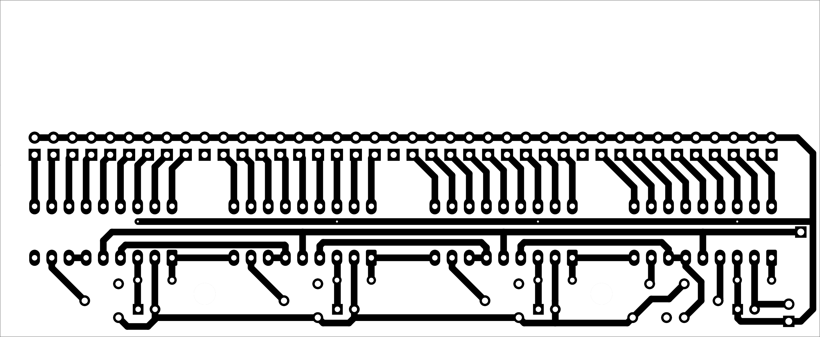
The PCB
Dimensions: ca. 12.1 x 5 cm. Bottom connections are turqoise, brown are top connections. There is space at the top for a scale.
Click to enlarge.
Parts list
| C1 - C4 | 10M/25V |
| D1 - D40 | LED |
| J1 | pin header 1x02, raster 2.54 mm |
| J2 | pin header 1x01, raster 2.54 mm |
| R1 - R4 | 10k |
| R5 - R8 | 20k, SMD 0603 |
| R9 - R12 | 680, SMD 0603 |
| RV1 - RV5 | potentiometer for PCB, 10k |
| U1 - U4 | LM3914N |
This is how it looks like in a finished construction: