Switch-mode power supply 12 V and 5 V with FSDM0565R
I built this power supply from used parts pulled from Asus LCD monitors. I used the service manual and FSDM0565R datasheet for reference.
Parameters:
- input: line voltage 230 V
- outputs: 12 V / 0.4 A and 5 V / 3.5 A
The transformer is of type SPI 8TT00048 and there is no data on it, as usual. Pins are tied to doubles on the secondary, GND is in the middle.
The main winding that is used for reference, is 12 V and the supply works correctly only if this rail is loaded.
My measurements when only one rail was loaded:
- 12 V rail: 11.4 V 0 A, 10.7 V 0.1 A, 10.3 V 0.2 A, 10.1 V 0.3 A, 9.8 V 0.4 A
- 5 V rail: 5 V 0 A, 4.9 V 1 A up to 1.2 A, then it turns off
When I loaded the 12 V rail with a 68 ohm power resistor, it supplied 150 mA without 5 V rail loaded, however, the current increased to 190 mA when taking maximum current (3.5 A) from the 5 V rail.
- 5 V rail with 68 ohm resistor on the 12 V rail: 5 V 0 A, 4.9 V 1 A, 4.8 V 2 A, 4.6 V 3.5 A, when it turns off
So the end result is that for some reasonable current from the 5 V rail, the 12 V rail must be loaded.
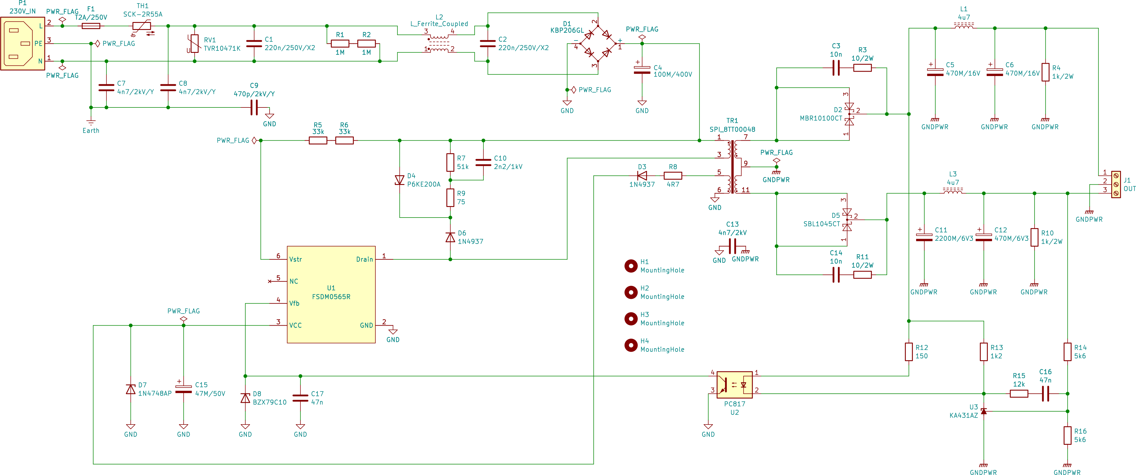
The schematic
Click to enlarge.
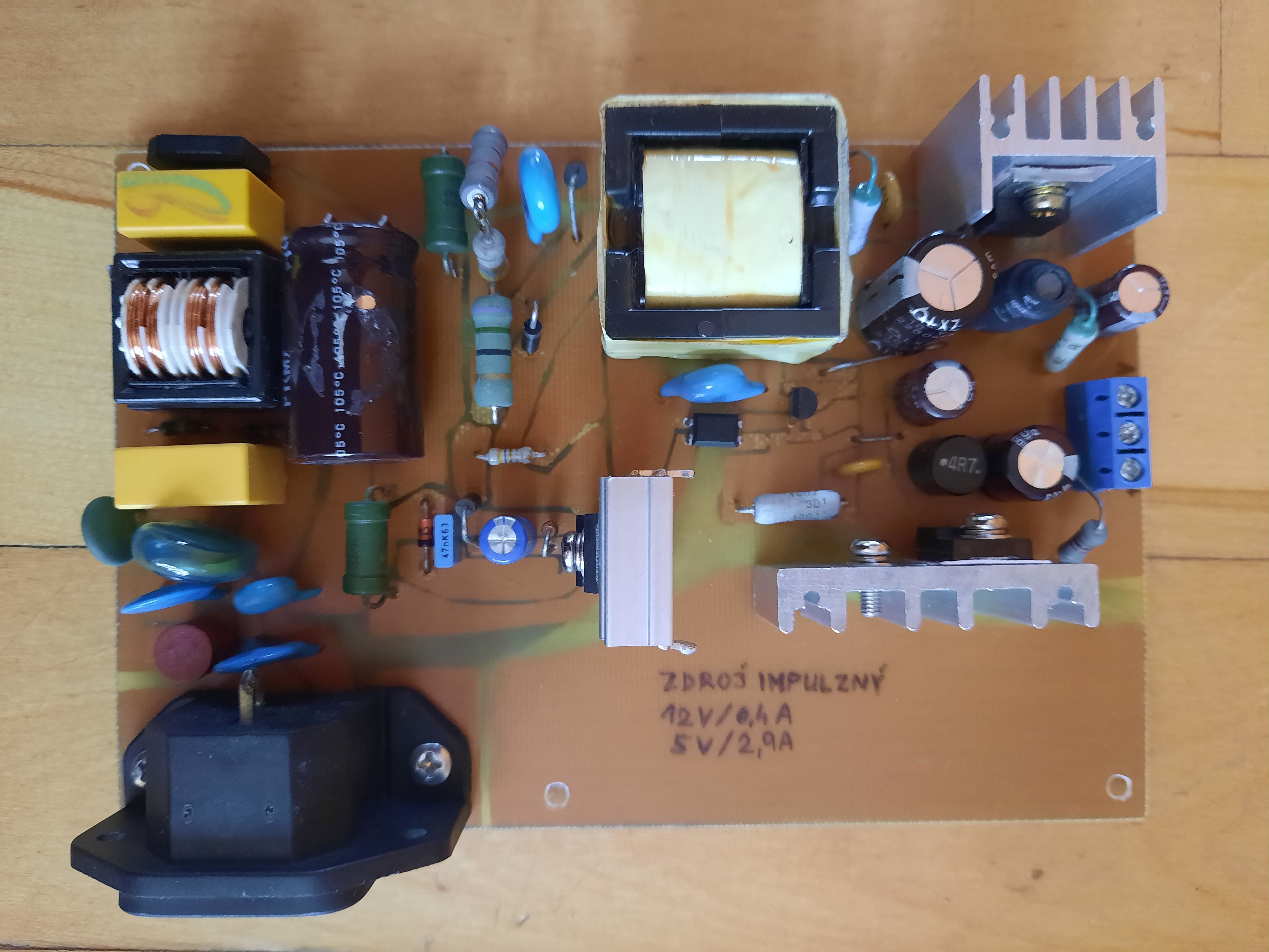
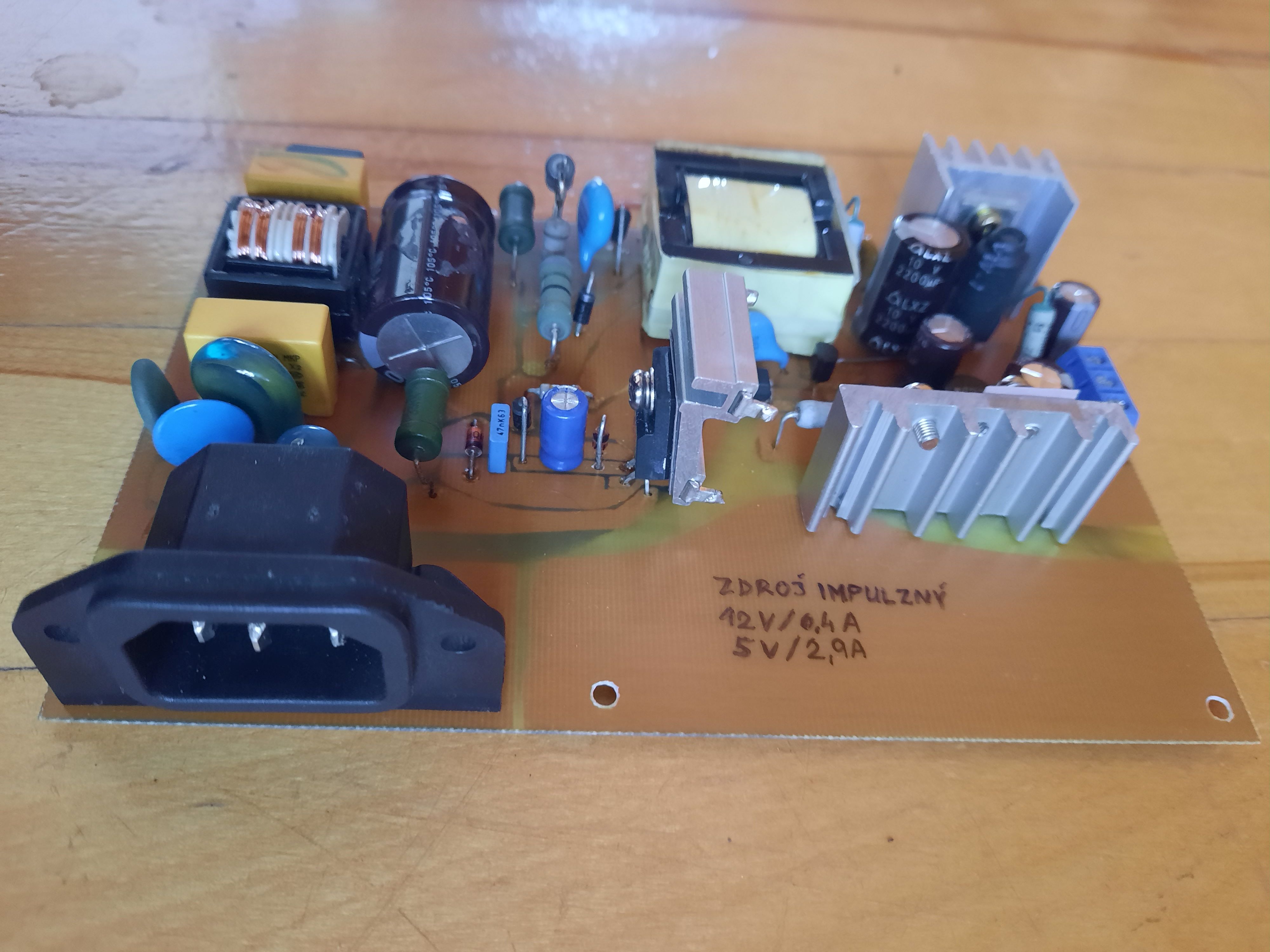
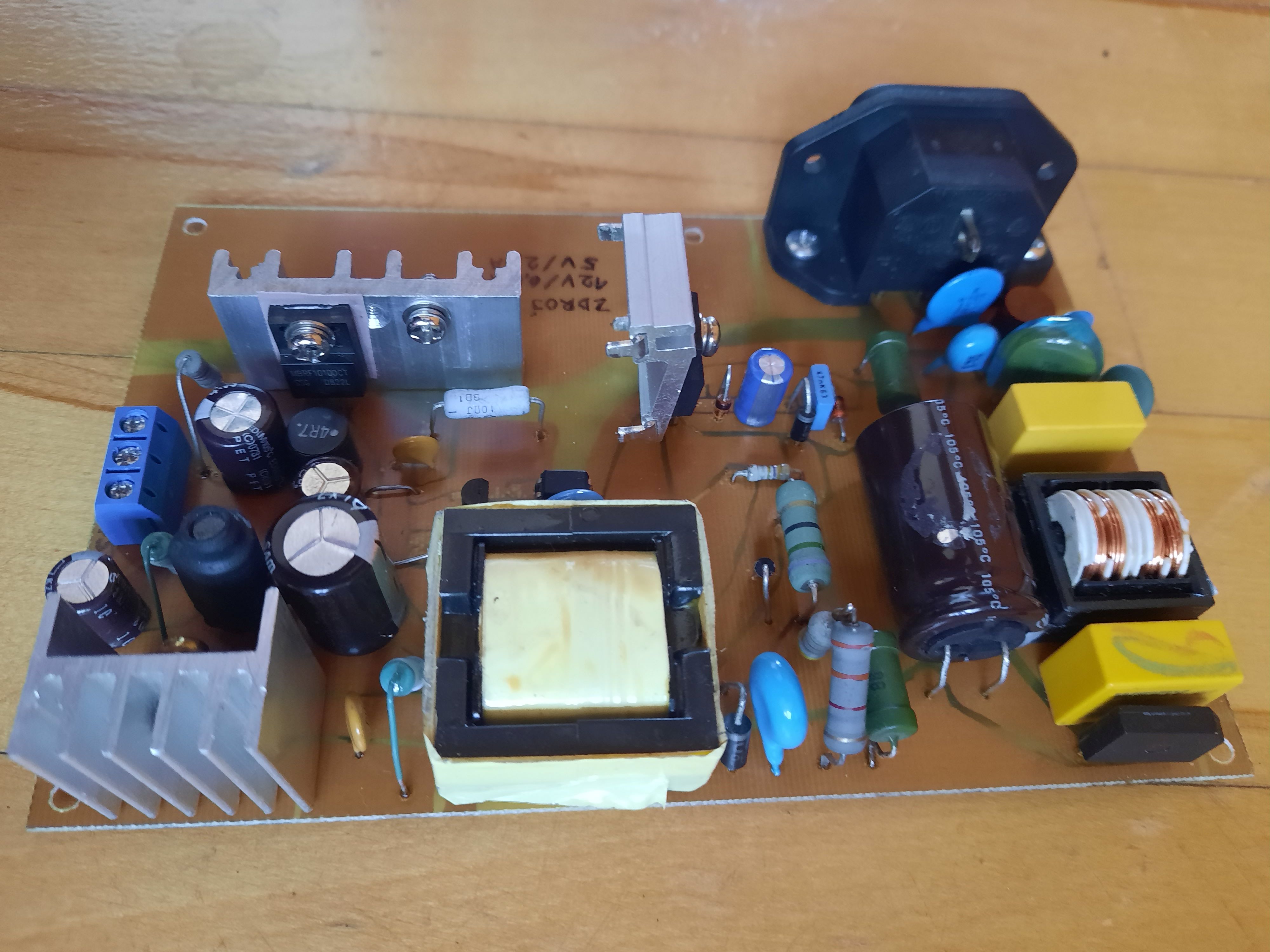
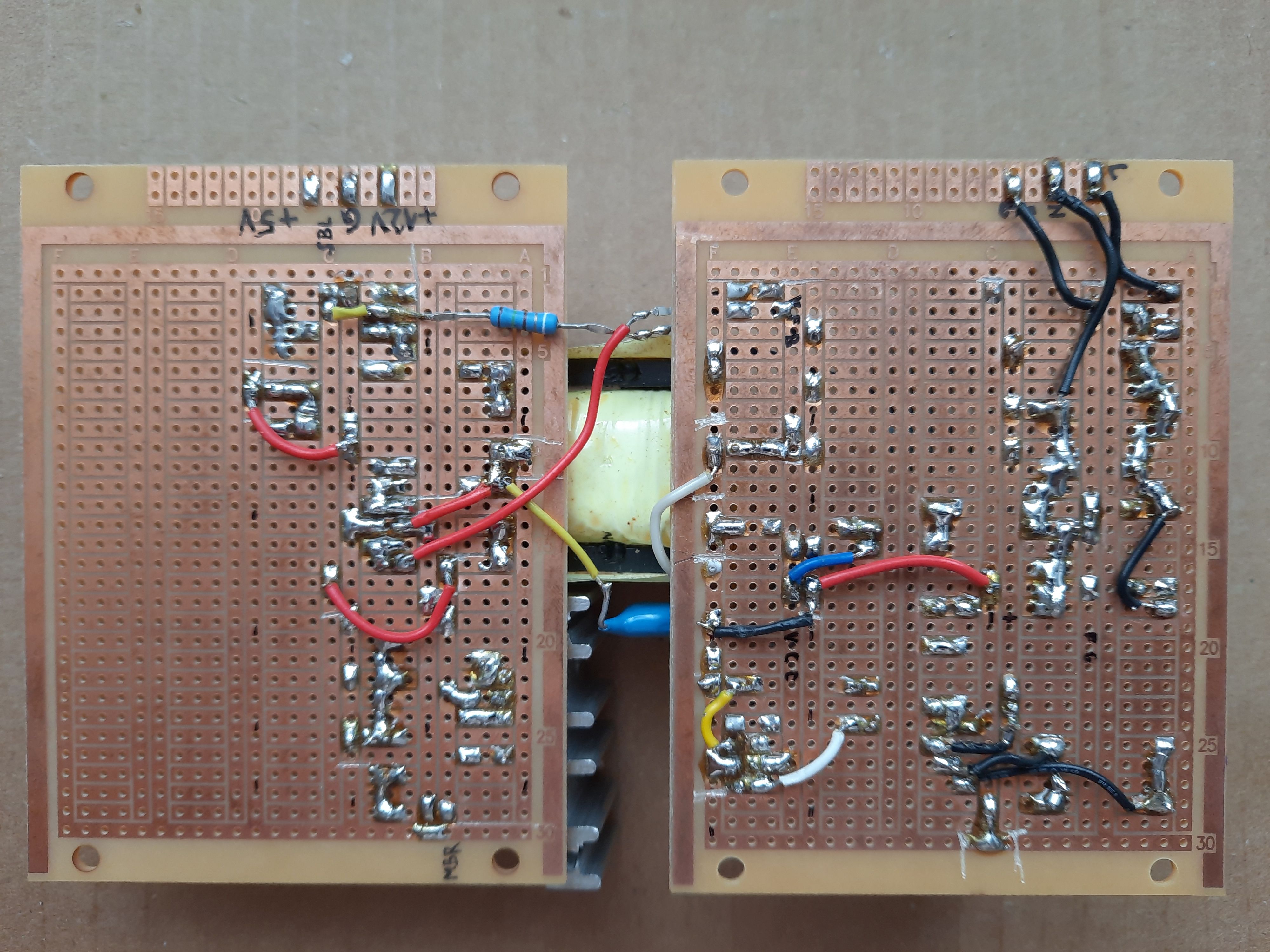
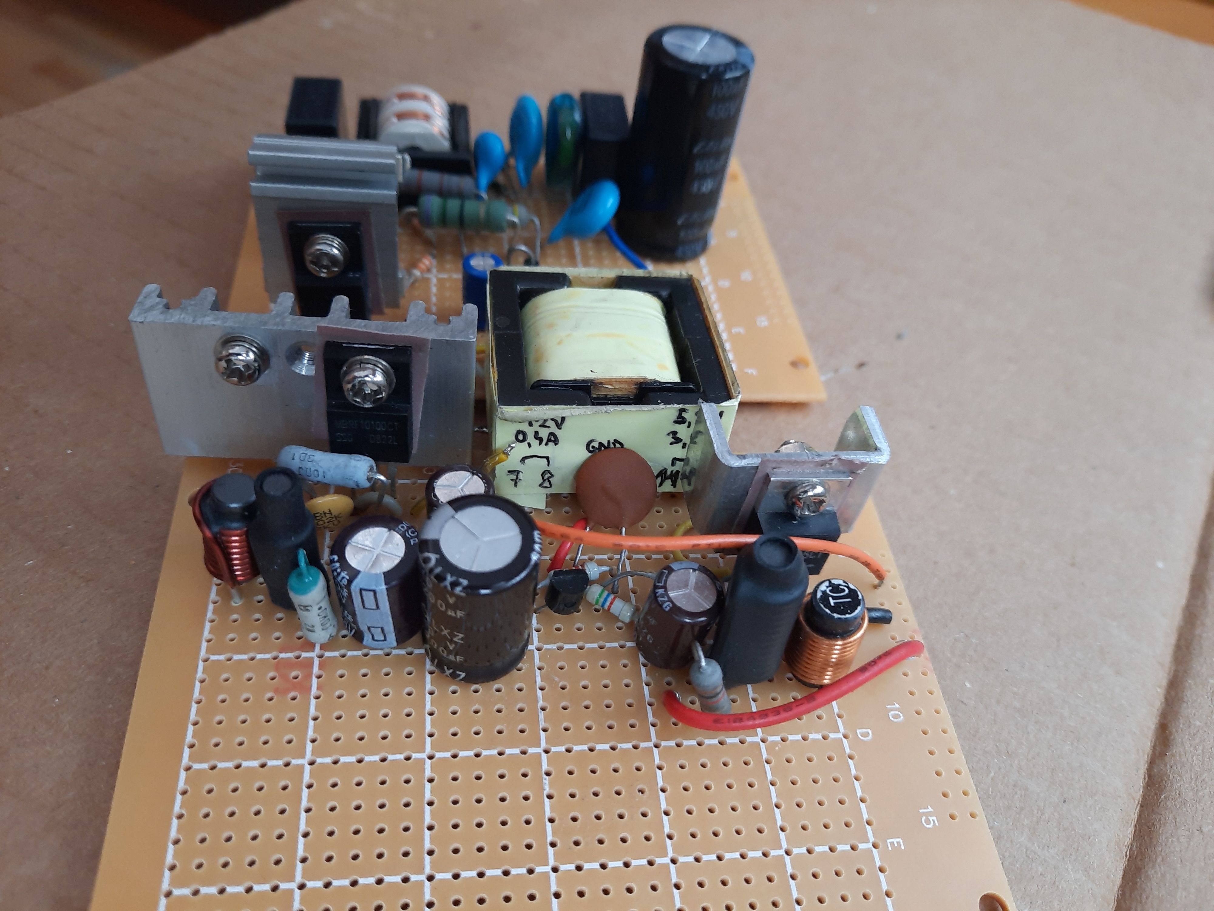
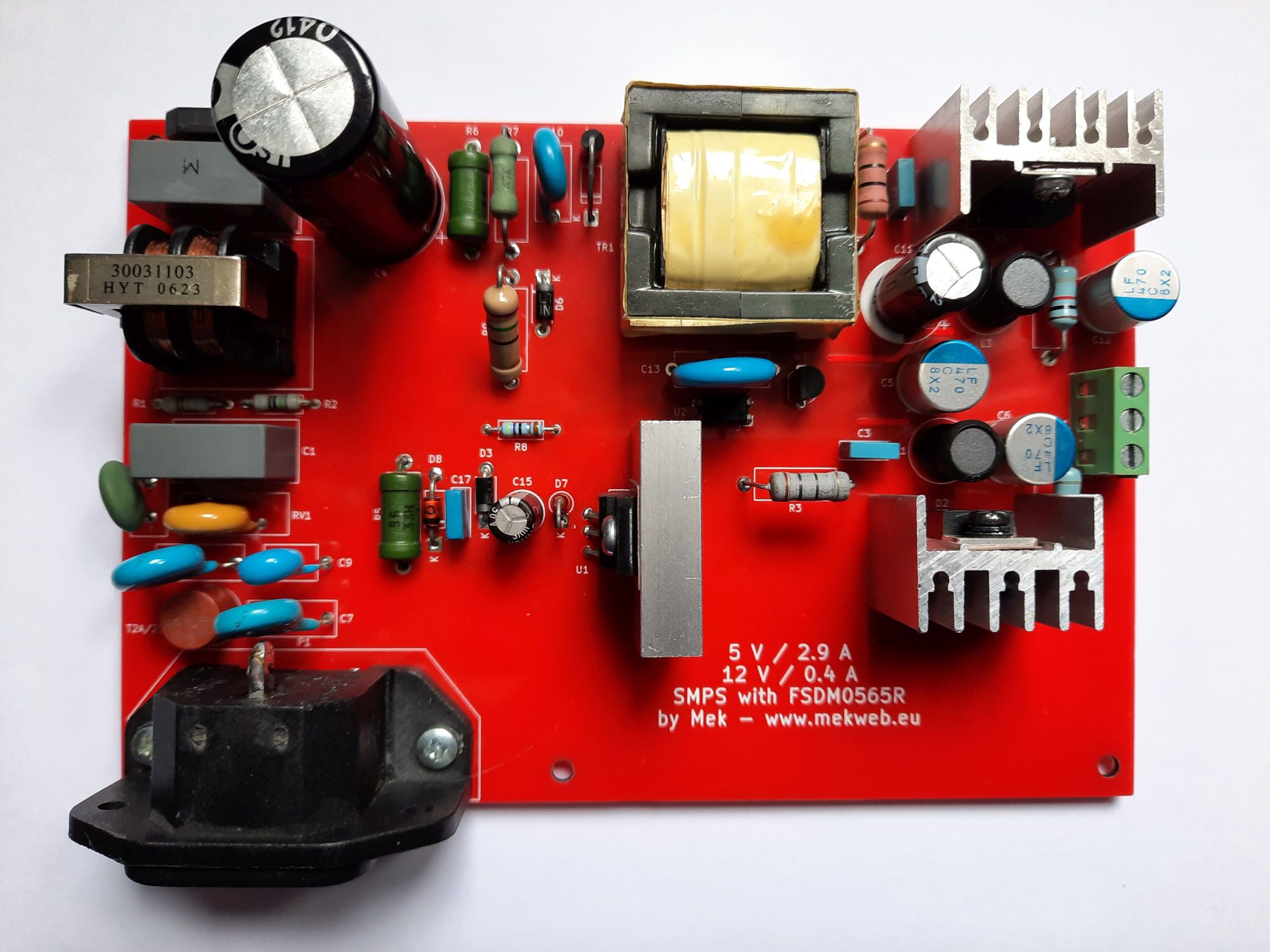
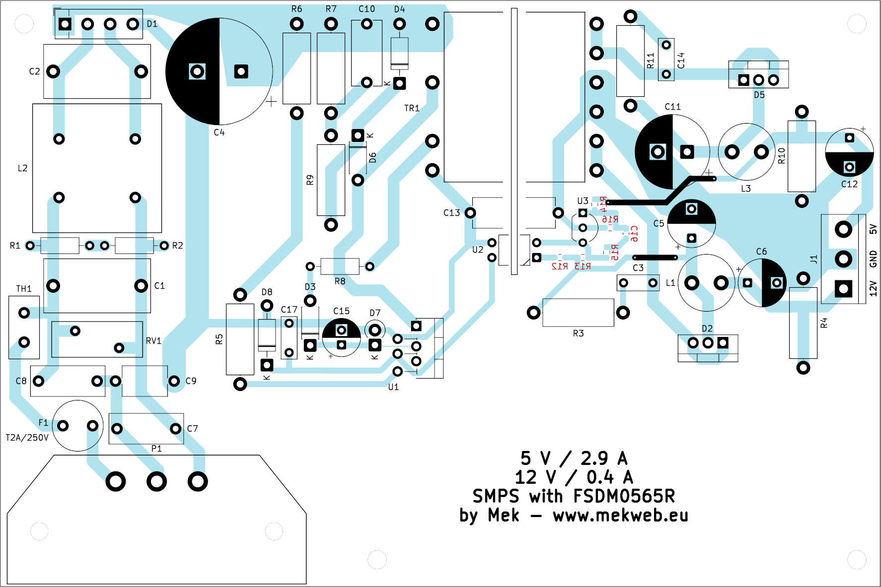
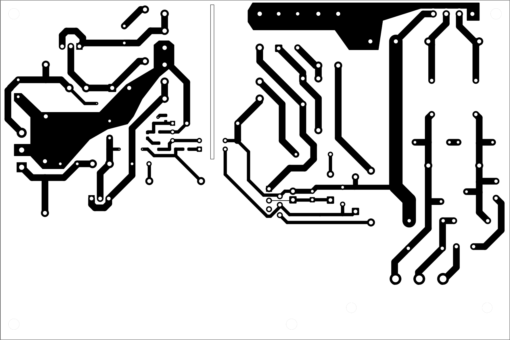
PCB
Dimensions: 15 x 10 cm. Bottom traces are turqoise, top traces are black. The red SMD parts are soldered from below.
Click to enlarge.
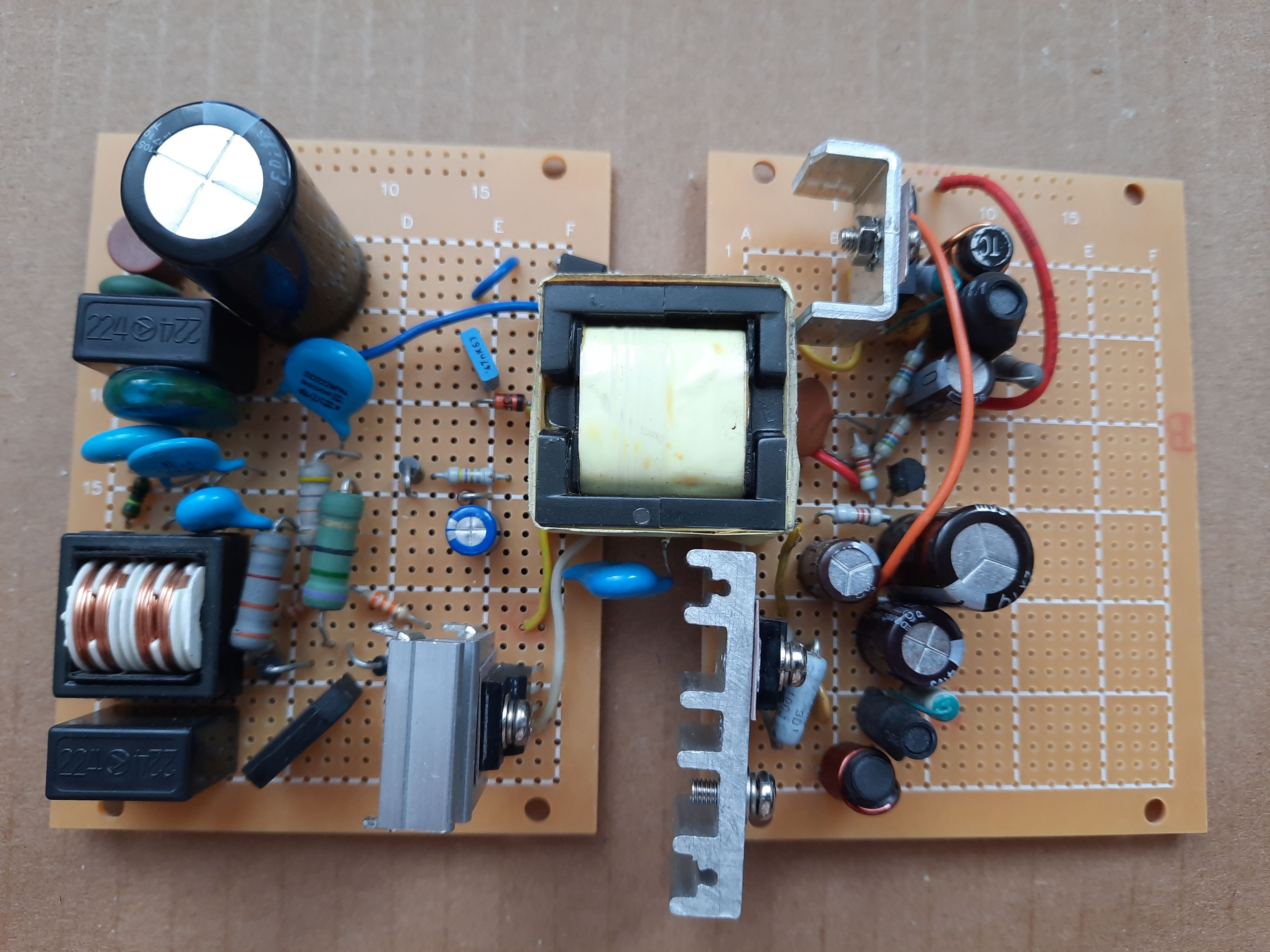
Conclusion
I played with this circuit because I had many parts from dismantled SMPS power supplied and I succeeded in building one. The transformer is buzzing with high-pitch tone, like almost any pulse transformer does, but it is barely hearable. At first I built the circuit on a home-etched PCB, then I ordered profesionally made PCBs (red), as I had multiple sets of parts including the transformers. This power supply might come handy to power some custom construction in the future.