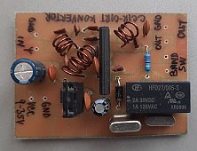
FM CCIR-OIRT converter with switchable ranges
While repairing old radios, it often happens that FM uses the old Russian norm - OIRT - that is no longer used. OIRT range is 65 - 74 MHz. Our broadcast stations use CCIR, 88 - 108 MHz. Sometimes the original FM input circuit cannot be re-tuned, or it would be too hard, or the receiver would lose its sensitivity. In these cases, it's worth building in this converter that converts CCIR stations into the OIRT range.
However, OIRT range is smaller than CCIR, so not all of it can be converted. Ususally the owner of the receiver chooses which sub-range of CCIR is most interesting to him, and chooses an appropriate crystal in the converter - the crystal decides by how many MHz the CCIR stations are converted down.
DIY kits of such converters are in commercial sale, and I also bought some. They are manufactured by Jabel - Poland, type J-246. This construction is based on that DIY kit. I added a possibility to switch between two frequency ranges that are switched by a relay. Otherwise parasitic inductances and capacitances of cables for the band switch could play a bad role in the circuit.
Band switch can be placed in some non-critical place, such as on the back of the receiver, so that original design is not disturbed. The converter itself should be placed inside the radio (if there is enough space), between the antenna input and antenna input of FM input circuit. PCB of the converter should be placed in a shielded box.
More detailed guide in Polish is included in the archive for download at the bottom of this page. A guide in English does not exist.
Parts
Compared to the commercially available DIY kit, I also changed the voltage stabilizer (7805) with a more powerful one. That's because the relay can take more current, depending on relay type - it's a standard mini relay with 5 V coil and DPDT switches (but only one switch is used). If there is a 5 V voltage in the receiver that can be readily used, the stabilizer can be omitted. Otherwise, you can use any DC voltage between 8 and 25 or 35 V (depending on your specific type of 7805).
Instead of LA1185, also TA7358 or AN7205 can be used.
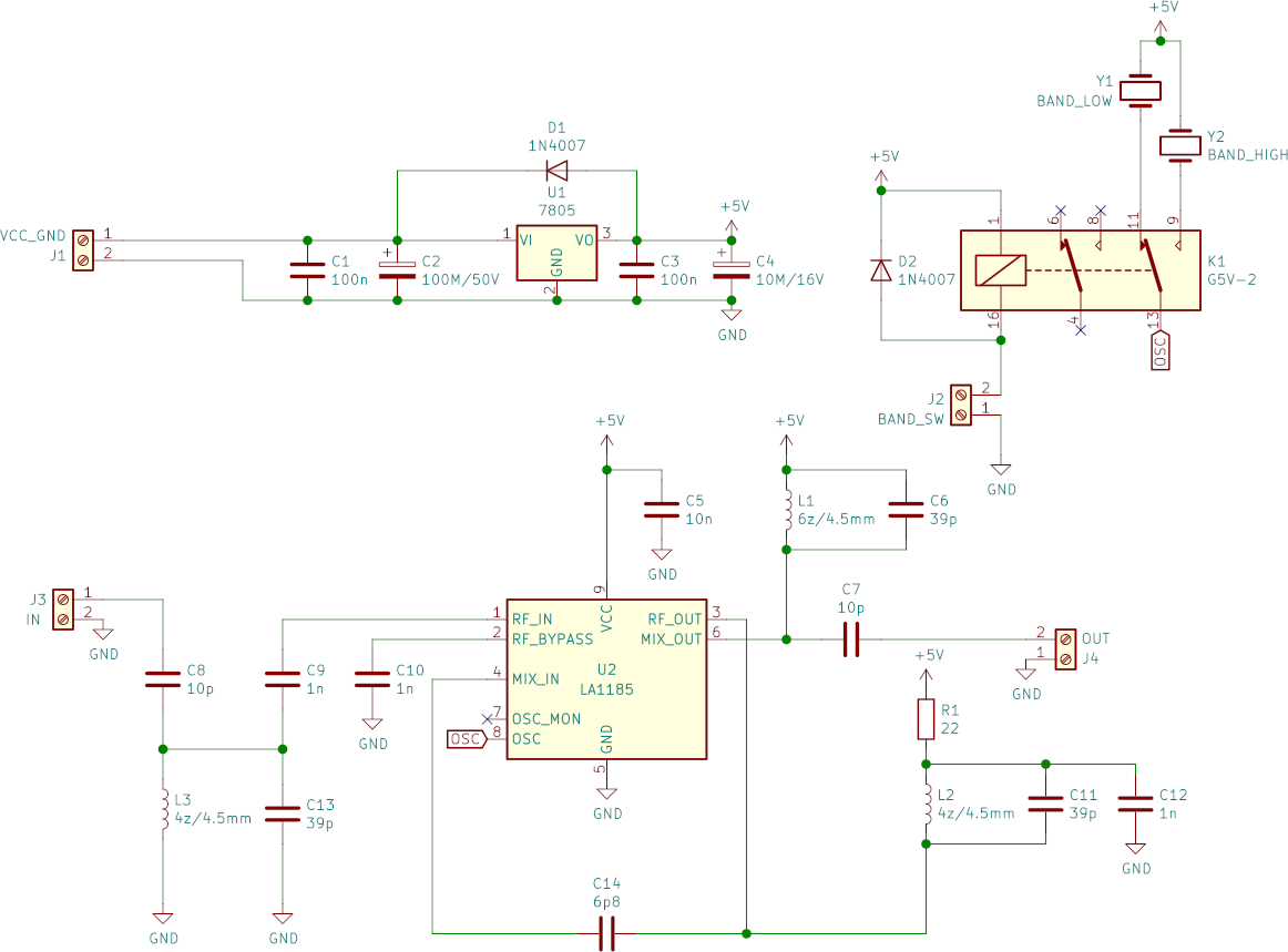
All coils are air coils, internal diameter is 4.5 mm, enameled copper wire of 0.7 mm diameter. Turn counts are in the schematic.
Despite of the converter being double-range, it's not possible to use all of the CCIR range, because it is slightly wider than two times of OIRT. In this case, triple-range would be better, but it would make the circuit much more difficult.
Choose the crystals according to sub-ranges of CCIR range that are most interesting to you. There are multiple variants that can be used with crystals of common frequencies that are sold or can be scavenged from old electronics. But beware - not all crystals work in the converter. For me, only the ones in lower casing worked (HC-49S).
Variant 1
- Crystal 1: 20.25 MHz - range 86.25 - 94.25 MHz
- Crystal 2: 27 MHz - range 93 - 101 MHz
- or maybe 33.8 MHz - range 99.8 - 107.8 MHz
Variant 2
- Crystal 1: 24 MHz - range 90 - 98 MHz
- Crystal 2: 30 MHz - range 96 - 104 MHz
This is the schematic (click for larger version):
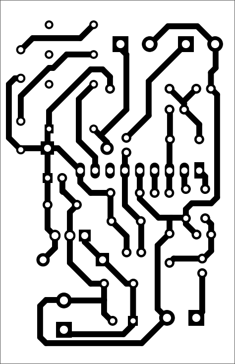
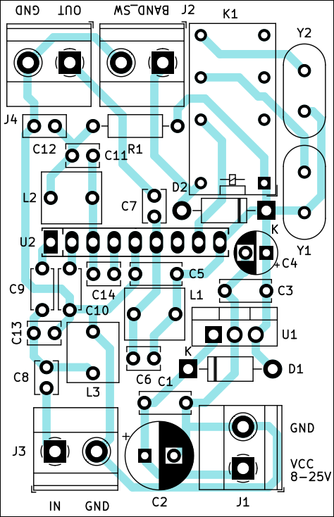
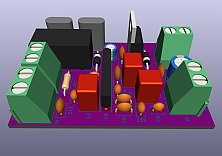
And the PCB. Dimensions are 40 × 62 mm.
First run
After soldering all parts and usual checks, connect the power supply. Watch power consumption - if it's reasonably low (below 100 mA), then all is probably OK.
All three coils need to be tuned for best reception. That is best done by using an SDR connected to a PC. Connect the antenna input of the SDR to output of the converter. You should see FM broadcast stations in the OIRT range 65 - 74 MHz. Stretch or squeeze the coils to get best reception in this range. In my case, I had to stretch L1 more significantly - see photos below.
Short out the BAND_SW terminals. The relay clicks, and then you should observe different stations in the OIRT range - according to the second crystal you used. All done :)
