FM receiver with TV tuner with manual tuning
The article starts below the video.
The same way as I wrote about digital tuners in this article, this second article is going to be about analog tuners, where tuning is performed by change of voltage level.
My tuner scraped from old CRT TV has designation "Sony BT-AC401", and, as I found out, it is compatible with other tuners from different manufacturers, such as:
- KSH1352
- UV1315
These tuners can tune frequencies from 50 MHz up to 850 MHz (rougly), which also covers the FM broadcast band. The whole band is divided into three bands: VHF1, VHF3 a UHF - marked as BL, BH, BU in the pinout. The tuner is switched to the band that has VCC input on its associated pin. I connected VCC to pin BL which means VHF1. Change of tuning voltage on the VT pin then covers frequencies 48,25 - 168,25 MHz, tuning voltage must be between 0 and 33V. Because we only want tuning in the FM broadcast band, tuning voltage is limited by resistors on both sides of tuning potentiometer. This also brought the positive effect of more sensitive tuning. Of course, tuning potentiometer should be a multi-turn one.
Pinout is standard among manufacturers. But beware, some tuners require 12V, other tuners 5V. It's always a good practice to search for a datasheet and go from there.
- AGC - this pin must have input from 0 to 4V (by potentiometer). Some stations are best received while AGC voltage is lower, other stations require full 4V.
- VT - tuning voltage for varicaps - 0-33V
- BU - UHF band (not connected)
- BH - VHF3 band (not connected)
- BL - VHF1 band (connected to 5V)
- +5V - supply voltage
- IF - asymmetrical IF output
GND does not exist as a pin (but some tuners may have it). The metal casing serves as GND.
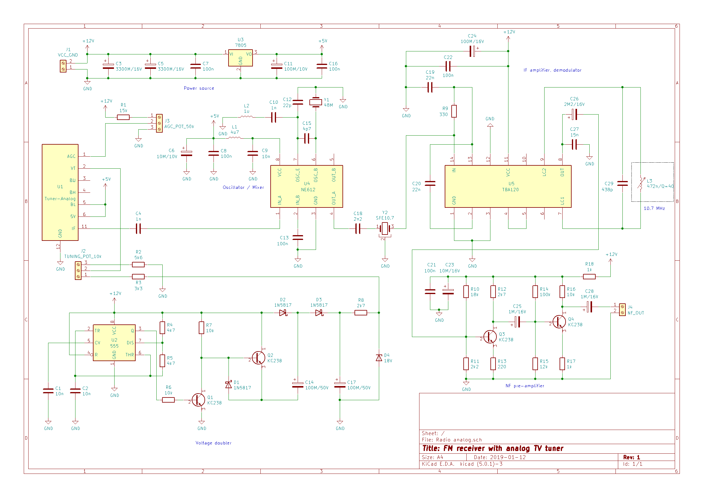
With the Sony tuner, I made a circuit with IF 10.7 MHz, demodulator TBA120 and transistor preamplifier, since the output was too weak..
Supply voltage is 12V, but a simple 555 DC converter doubles the voltage to 24V, which is stabilized by zener diode to 18V. There is no need for a higher voltage, because it would correspond to higher frequencies where there are no FM stations.
My second experiment was with a TV tuner pulled out from an old monochrome TV Tesla Pluto. This tuner has designation "TIP: MOSFET TJ01/M-ŠK IDENT; 580875 Made in Yugoslavia" and is compatible with tuners from production of Tesla and Hungarian Republic. Unfortunately, I didn't find any detailed information. Some of Tesla tuners are described in so-called technical information no. 38. However, I managed to find out the pinout by looking at the schematic of the TV. This tuner can tune only until 104 MHz in the VHF1 band, but on the other hand, has better selectivity. Pinout is as following:
- 4P - 4th program (not connected)
- 1P - 1st program (connected to 12V)
- AGC - this pin must have input from 0 to 9V (better regulated with a potentiometer)
- VT - tuning voltage for varicaps - 0-30V
- +12V - supply voltage
- 3P - 3rd program (not connected)
- IF - asymmetrical IF output
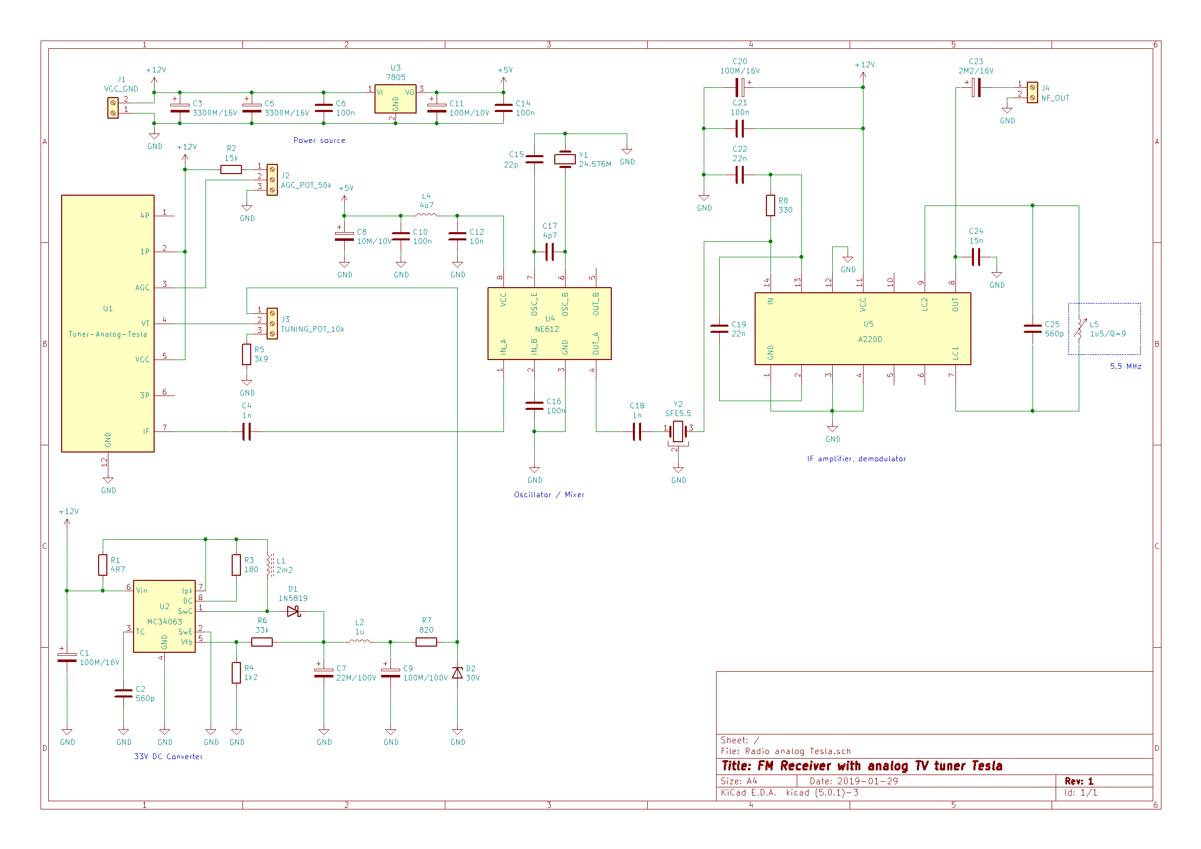
With the Tesla tuner, I made a circuit with IF 5.5 MHz and demodulator K174УP1 (A220D), output of which is strong enough, thus, does not require a preamplifier.
Supply voltage is 12V, which, for tuning purposes, is up-converted to more than 40V, to be stabilized by zener diode to 30V.
Both circuits require a so-called phasing LC circuit near the FM demodulator. This is also the only tuned circuit. In the first case, LC circuit must resonate on 10.7 MHz, in the second case on 5.5 MHz. I recommend this web page, to calculate proper L and C values, and measure selected components with a good LC meter. It is also best to measure the Q factor of the inductor, which should be around 40. However, in the second circuit I used an inductor with Q = 8 and it worked as well, so your mileage may vary.
If you decide to build this circuit, you will find the information about bringing it to life and tuning the LC circuit handy - see the article about digital tuners, the principle is mostly the same. As well as there, an SDR receiver for PC can help a great way if anything is not working (it is better to see one time than hear or read 100 times) - details are also written in the second article.
In the downloaded zip file you will find:
- datasheets of the Sony tuner and equivalents
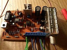
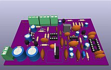
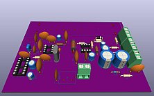
- KiCad projects of both circuits (Sony and Tesla), including schematic and PCB
I found out that the Sony tuner has a bit worse results than Tesla, but the Tesla one can tune only until 104 MHz. However, both give good results to satisfy an undemanding listener. A stereo decoder, RDS decoder, and any audio amplifier, can be connected to the output to enhance user experience.
I would definitely recommend these circuits also to the beginners. They can learn quite a lot and give a new life to components that would otherwise end up on the junkyard.
