Audio amplifier 10 W with AD52060
In consumer electronics (such as TV...) you can find audio amplifiers of class D, that are in a miniature SMD package such as TSSOP28. Even when the applicance is not working anymore, these integrated circuits will probably still work and it is worth de-soldering them for later use.
I know, I know... class D... it's not for audiophiles. It's also clear that such class D amplifier modules are available from China for a few bucks... but where is the fun then?
This circuit is appealing by re-using of salvaged parts that would end up in the landfill, and building something useful. It can also be treated as a nice training for work with SMD parts.
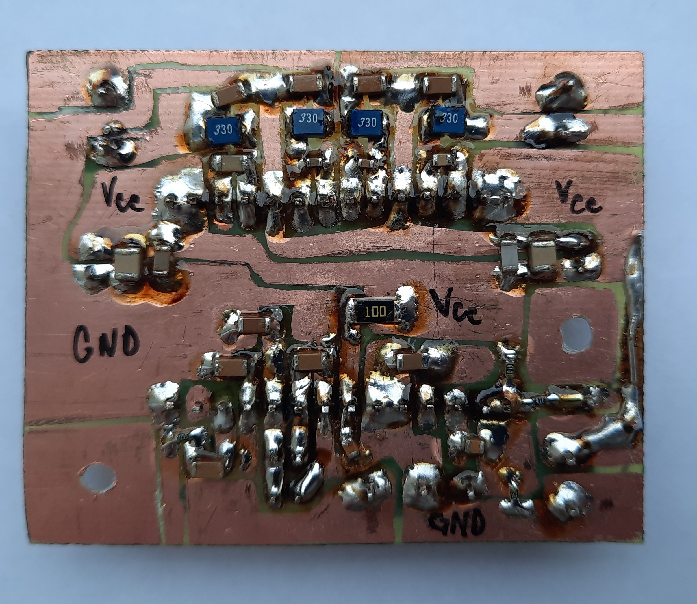
Class D amplifiers are known for their high efficiency thanks to their working principle - switching, similar to switch-mode power supplies (SMPS). No heatsink is required, thus, they can be really small. An ordinary customer doesn't take sound quality into account, so they are heavily used in consumer electronics (where "cutting costs" is the mantra), even in places where there is enough space to use something better. The disadvantage is that they are mostly manufactured only in SMD packages, require greater attention in PCB design and LC filters on output - because the same as SMPS, also a switched audio amplifier (class D) emits unwanted frequencies. Long PCB traces and wires can also cause instability and oscillation.
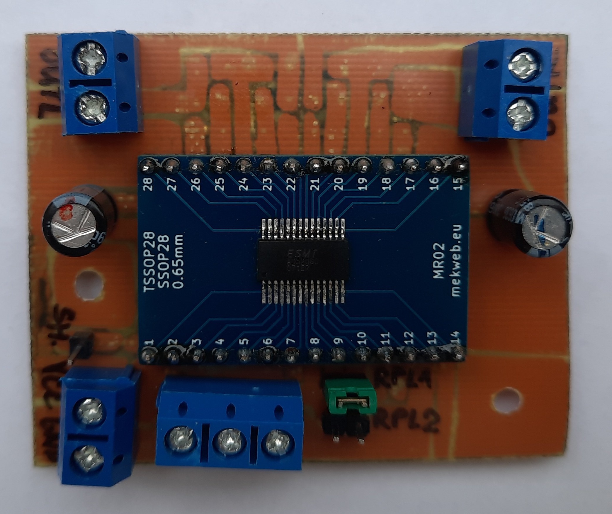
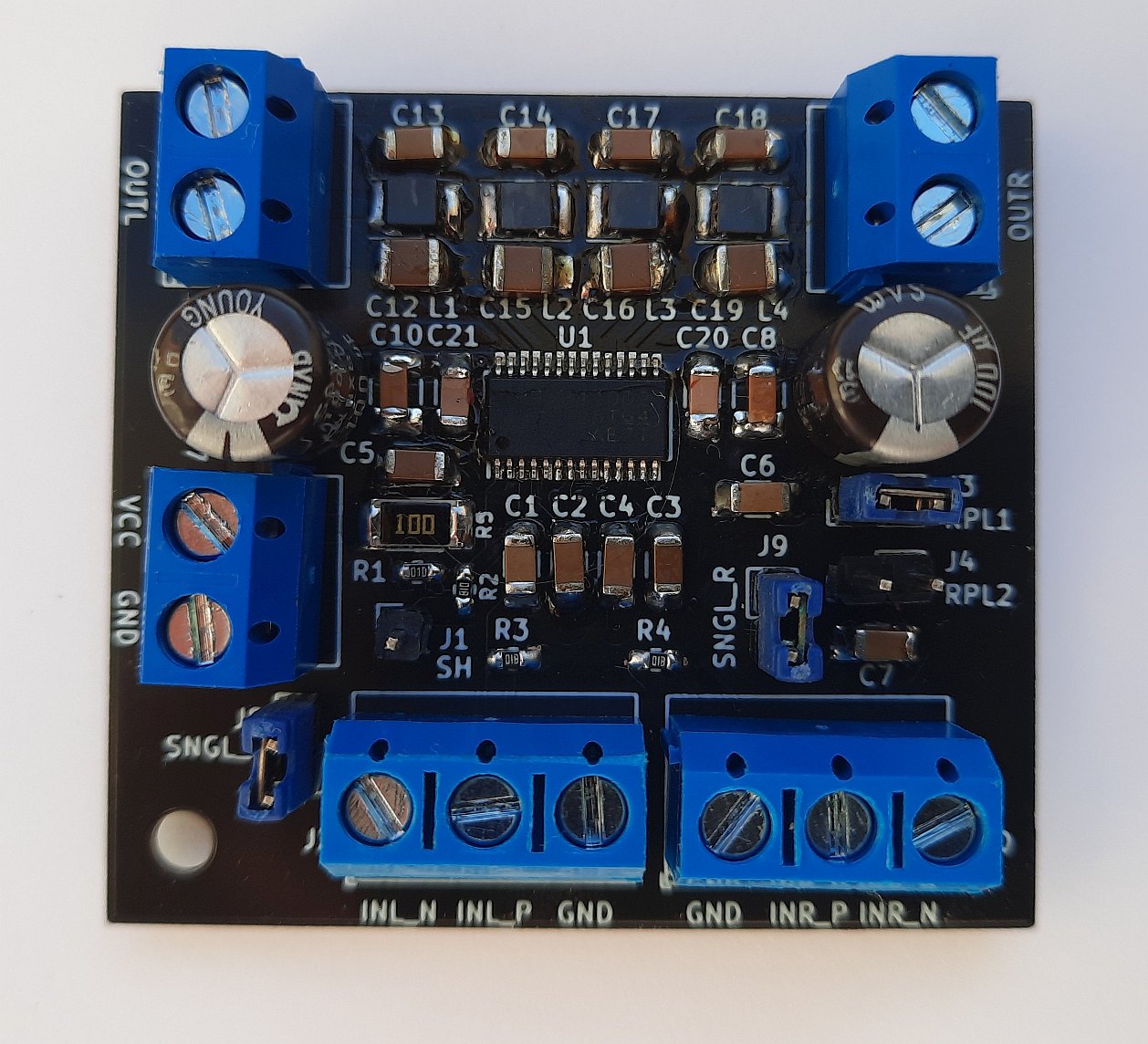
Integrated circuit AD52060 (in TSSOP28 package) is used in this construction. I de-soldered it carefully using a hot air de-soldering gun. An ordinary transformer soldering gun would not be up to the job, because the IC has a thermal pad on its bottom that is intended to dissipate head, is soldered to the PCB and not reachable from outside. Furthermore, I didn't want to bend the leads as they are already delicate enough and too near each other...
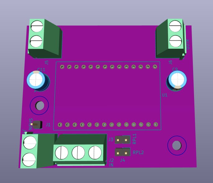
This PCB is not designed nearly ideal for a class D amplifier, but my accent was on easy reproducibility at home with regular DIY tools. That's why a one-sided PCB is also used. The IC itself is soldered on an adapter plate from TSSOP28 to a standard pin pitch of 2.54 mm that I designed and got manufactured already in the past. Distance between pin rows on the adapter is 8 positions on a breadboard, or 20.32 mm or 0.8 in. It's good to drill a hole below the chip before you solder it on the adapter plate to expose its thermal pad and later give it some more solder to dissipate heat more rapidly. I forgot to do this before soldering the chip on the adapter plate, and didn't want to go back anymore. The chip was then heating up too much on higher supply voltages and higher volume, and thermal protection turned it off.
Features
- Supply voltage: 8 - 26 V
- Power: stereo 10 W or 20 W depending on supply voltage and speaker impedance
- Speaker impedance: min 4,8 Ω for supply over 13 V, min. 3,2 Ω for supply under 13 V
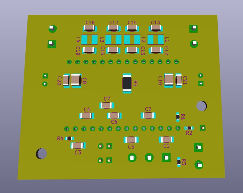
- PCB dimensions: 6 x 5 cm
- Shutdown pin
- Power limiting possible
- One-sided PCB
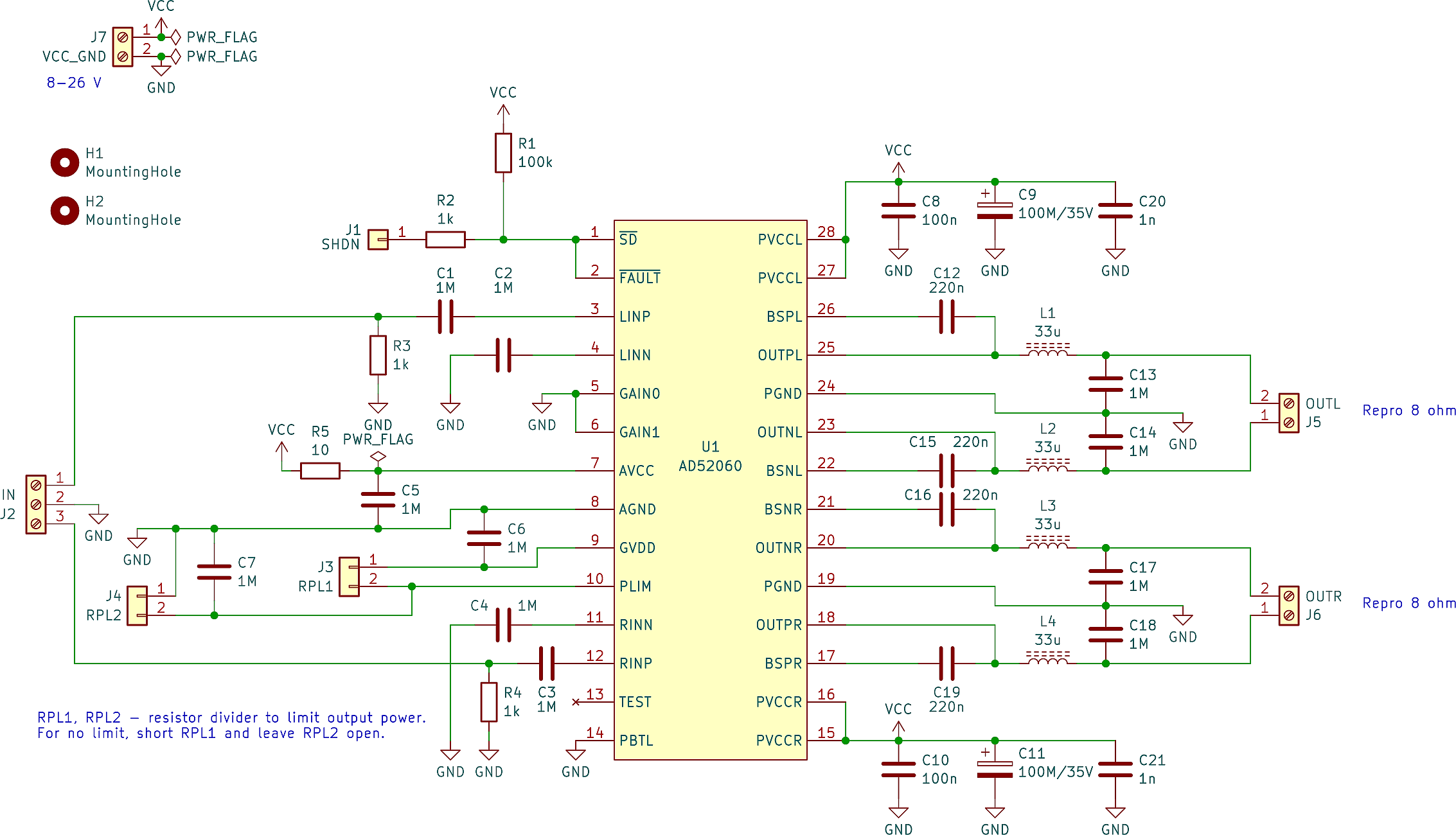
This circuit is designed for 8 Ω speakers. For a different impedance, parts in output LC filters should have different values. Refer to the datasheet for more details.
Schematic
Basically it's not different from the recommended circuit. Only the power limit function was brought out to two pin headers. It's possible to connect a resistor divider there (more in the datasheet), according to max. power limit that you want to achieve. Or, if no limit should be applied, short RPL1 (and leave RPL2 open).
Shutdown pin is "active low".
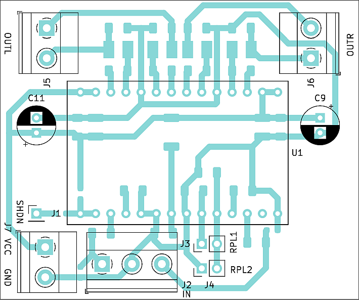
PCB on top:
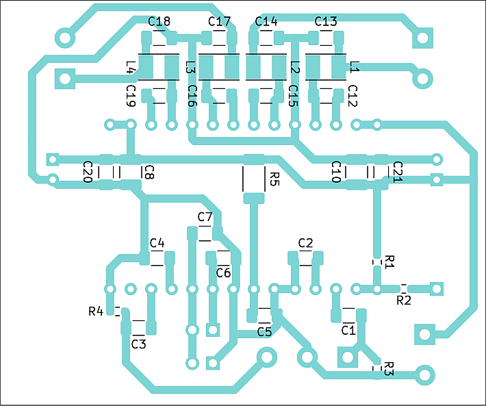
PCB on bottom (mirrored):
3D renders from CAD software, and photos how my construction looks like, are below.
The amplifier worked on first try. Surely it will find its place in one of my future constructions.
SMD variant
In the package for download below, there is also a KiCad project of a pure SMD variant of this amplifier - without adapter for the IC. In addition to the above, it has the following properties:
- support for single ended / balanced input
- pure SMD
- PCB dimensions 5 x 4,5 cm
- double-sided PCB
I found out that there are more ICs than just AD52060, that use the same pinout and connection of outside components, for example TPA3110D2. I tried it also on the SMD board and it worked. The SMD variant PCB cannot be made at home, but if you have access to appropriate equipment or can order PCBs from a specialized company, it may be useful.