Battery capacity tester
This battery capacity tester is intended for cells under 5 V, for example Lí-On, Li-Pol, rechargeable AA, AAA... batteries. It is useful to detect cells with fake capacities where real capacity is less than declared (often when buying via internet), or for sorting Li-On cells from old notebook batteries - some are still usable, while others should be trashed (recycled, to be more precise).
It is based on the circuit by MyVanitar and there is also a video. I made small improvements, such as:
- change of MOSFET type (I didn't have the recommended one)
- LM358N supply is 12 V instead of 5 V
- change of resistor for display backlight
- change of load resistor from 3 Ω to 33 Ω and 3,3 Ω in parallel, which are more common resistor values and give 3 Ω resistance as result
- change of buzzer with a common one from microwave oven, as the recommended one must have had beep generator built-in and I didn't have such one (+ change in Arduino code), adding some beeps as feedback
- settable cutoff voltage (originally it was hard-coded)
Features
- Max. voltage of tested battery: 5 V
- Max. discharge current: 523 mA (but can be changed by changing Arduino code and value of load resistor)
- Discharge current setting in 16 steps
- Settable cutoff voltage
- Power supply: 12 V DC or 12-18 V AC, 100 mA is enough
- Display: 16x2 standard LCD display
- No SMD parts, can be made at home easily
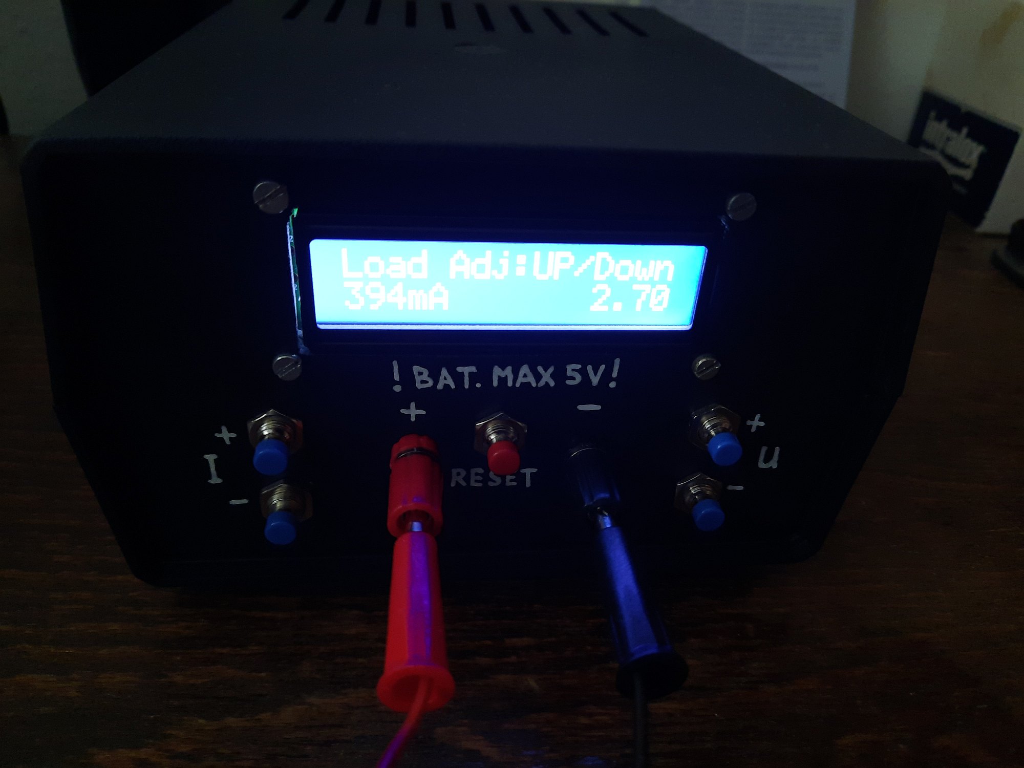
Control
After turning on, there is a short greeting message and then you have the options to set discharge current and cutoff voltage by buttons. At this time, you should remember that:
- battery must be connected at this time, not after timer is started
- discharging is started immediately when battery is connected (using presently set discharge current)
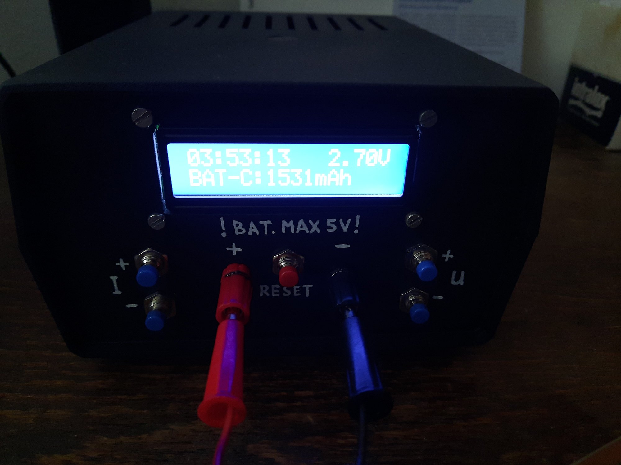
When both settings are satisfying, timer should be started by long- pressing the I+ button. There is a beep and time starts counting. Every second, battery voltage is monitored and shown on display. When battery voltage drops below the cutoff voltage, timer and discharging is stopped and capacity in mAh is displayed by calculation from elapsed time and constant discharging current. At the same time, a long beep draws your attention that the process has finished. To test another battery, cycle power or press the RESET button.
Circuit description
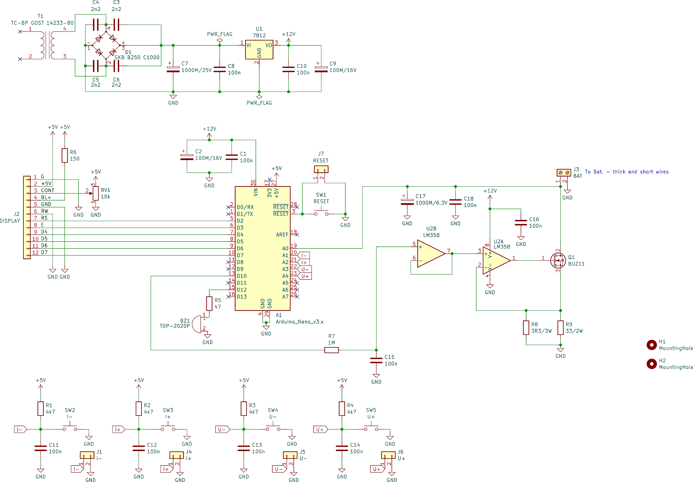
The circuit is driven by Arduino that generates a PWM signal which, through an RC element drives LM358N which in turn drives the MOSFET that opens only to the point to allow preset current to flow through it. It is basically a constant current load driven by Arduino.
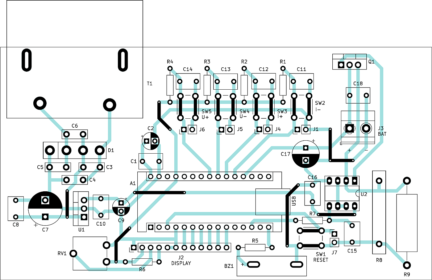
The PCB is single-sided and its dimensions are 13 x 7 cm. It is designed to fit into Z2AW universal enclosure. There is also a rectifier and 12 V stabilizer on the board, also with a transformer. That one is very specific, I perhaps pulled it out from an old Russian radio, type is TC-BP GOST 14233-80. Its secondary winding goes directly through the board and is soldered. Primary winding is connected by cables on top of the transformer. Of course, anyone building this circuit can use a different suitable transformer, and just connect its secondary to the expected points on the PCB. A weak transformer is sufficient, provided it can deliver 100 mA with at least 12 V AC (so that there is a reserve for 12 V stabilizer), but check transformer voltage when there is no load first, so that its voltage doesn't go too high.
From the drain and source of MOSFET to the battery and GND, there should be thick and short wires, because every milliohm matters for measurement precision. The MOSFET also needs a heatsink, but it doesn't have to be large at these currents, and no fan is required. Original circuit suggests IRF3710 but I didn't have it at home. I tried IRF3205 but current regulation only worked up to 120 mA with it. After reading comments from other people, I saw that I was not the only one and they suggested trying different MOSFETs and also to change supply voltage of LM358N to 12 V. These two amendments helped and current regulation worked like a charm. I used MOSFET type CEP50N06, but BUZ11 is in the schematic, which worked for me as well, and is much more common/available.
Schematic:
PCB from top with component placement:
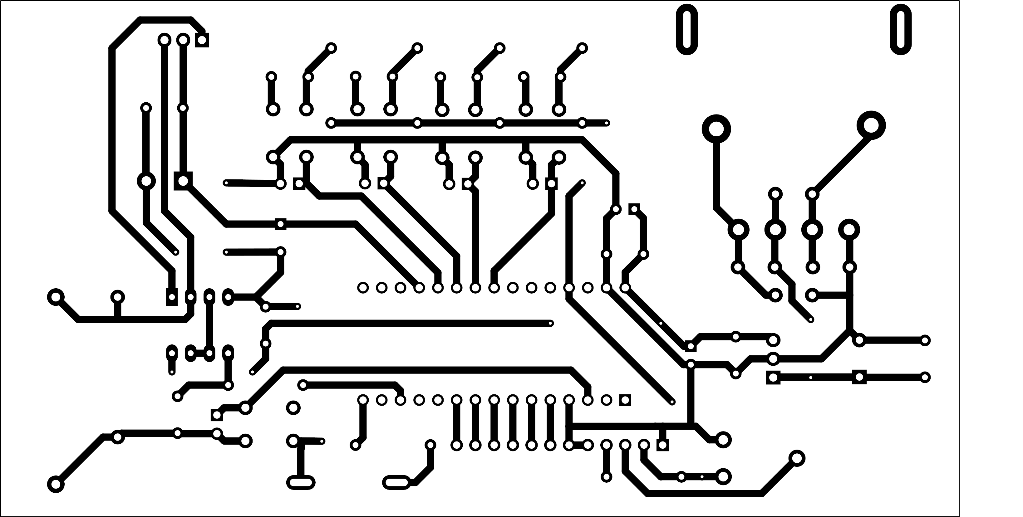
PCB from bottom (mirrored):
When all is done, it is good to measure exact current drawn from a battery in each of predefined current levels, and amend values in Arduino code according to them. They are in the Current[] variable - the real values may differ from mine, depending on component tolerances.
Apparently from the schematic, battery input is not protected from overvoltage or polarity reversal - beware of these when using the tester. It is a price to pay for circuit simplicity.
All materials can be downloaded below - pictures, PCBs, Arduino code and KiCad project. Personally, I am satisfied with this circuit. Besides a few details, I used components I had at home and didn't have to make additional purchases. Now I have another useful testing instrument at my home. I can happily recommend it.