FM receiver with TV tuner with digital tuning
The article starts below the videos.
For a longer time already, when disassembling old TVs for parts, I was thinking if the tuner could be reused somehow. I searched on the internet and found out that some people had variable success, and there was even a diploma thesis about this topic. However, there is little to no information on the internet, or only scarce info here and there, but no complete write-up of practical usability. That's why this article was written.
In short, there are two kinds of tuners, divided by tuning type
- analog - 0-33V is applied on one of the tuner pins, this is used to feed the internal varicaps
- digital - or PLL tuners - the frequency is told to the tuner by I2C bus
This article covers digital tuners. The one I have is TUNER WSP (PLL) TAEA-G041D 30048475 609A0611. I found out that it is the same tuner (or replacement) as for example
- KS-H-148E
- UV1316
- VESTEL 30048475
These tuners can tune frequencies from 50 MHz up to 850 MHz (rougly), which also covers the FM broadcast band. The receiver I am describing on this page, is limited to 87.5 MHz - 108 MHz (CCIR), because there is no FM broadcast on the other bands, and also different demodulators and filters would be needed for other modulations. However, the band can be easily adjusted to include the OIRT band, for example, by editing the ATmega88 code.
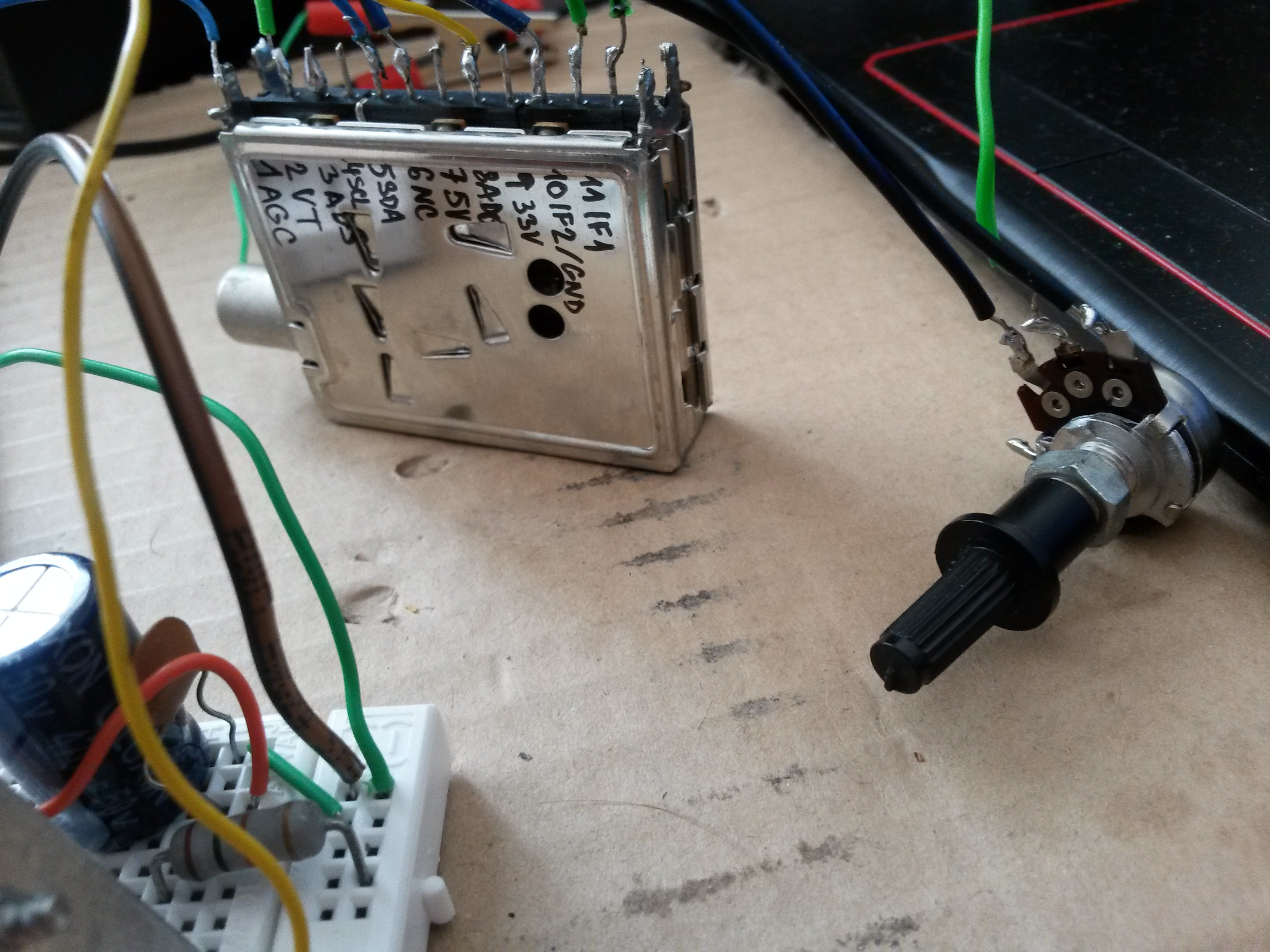
Pinout is standard among the manufacturers.
- AGC - this pin must have input from 0 to 4V (by potentiometer). Some stations are best received while AGC voltage is lower, other stations require full 4V.
- VT - tuning voltage output, not connected
- ADS - designation of tuner's I2C address, the address will be C2 if this pin is left unconnected
- SCL - I2C clock pin
- SDA - I2C data pin
- NC - not connected
- +5V - supply voltage
- ADC - not connected
- +33V - supply voltage (can be 29-35V)
- IF2 - symmetrical IF output, pin 2
- IF1 - symmetrical IF output, pin 1
Tuners exist with asymmetrical output, where pin 10 is connected to GND. This circuit uses a symmetrical tuner.
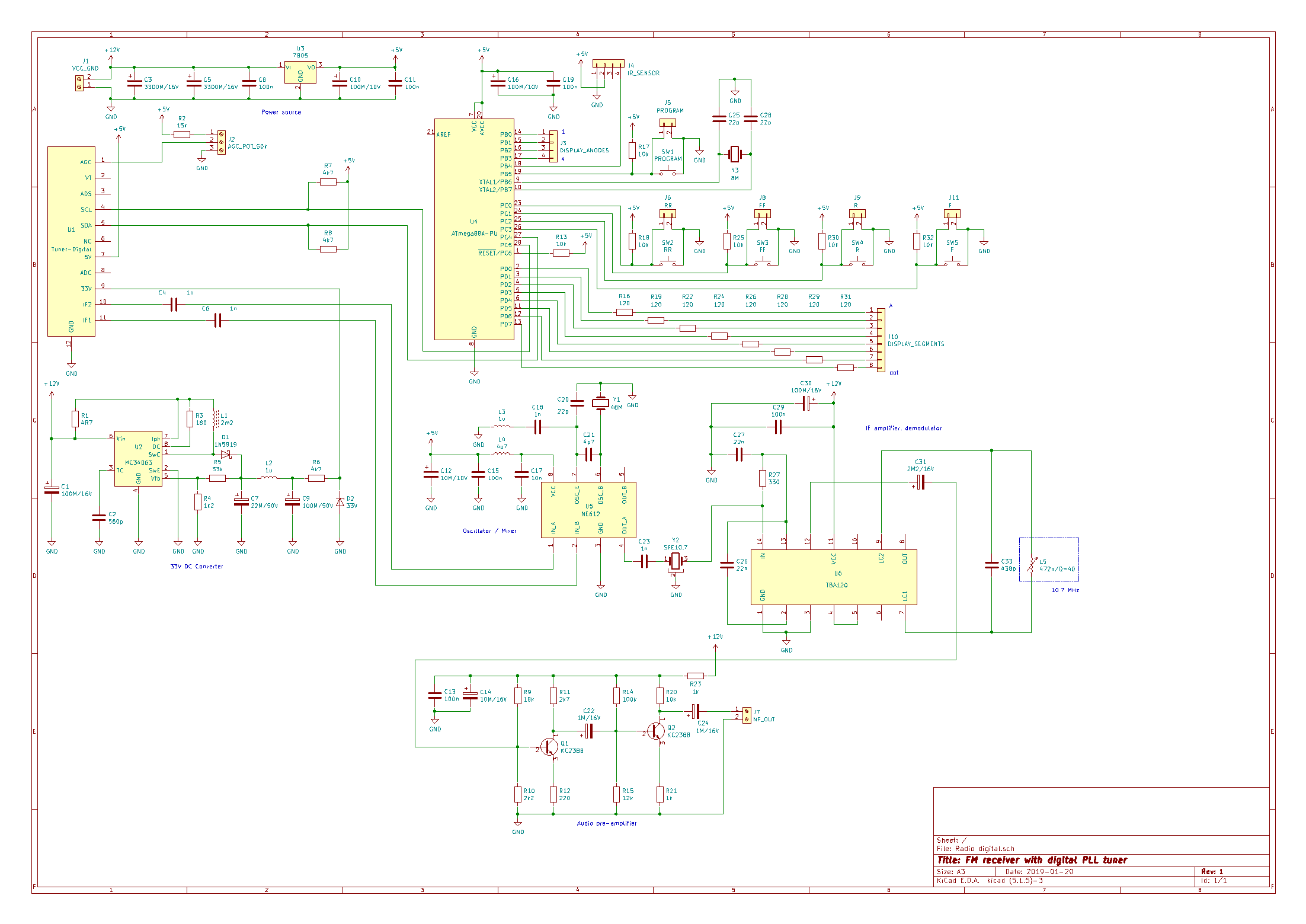
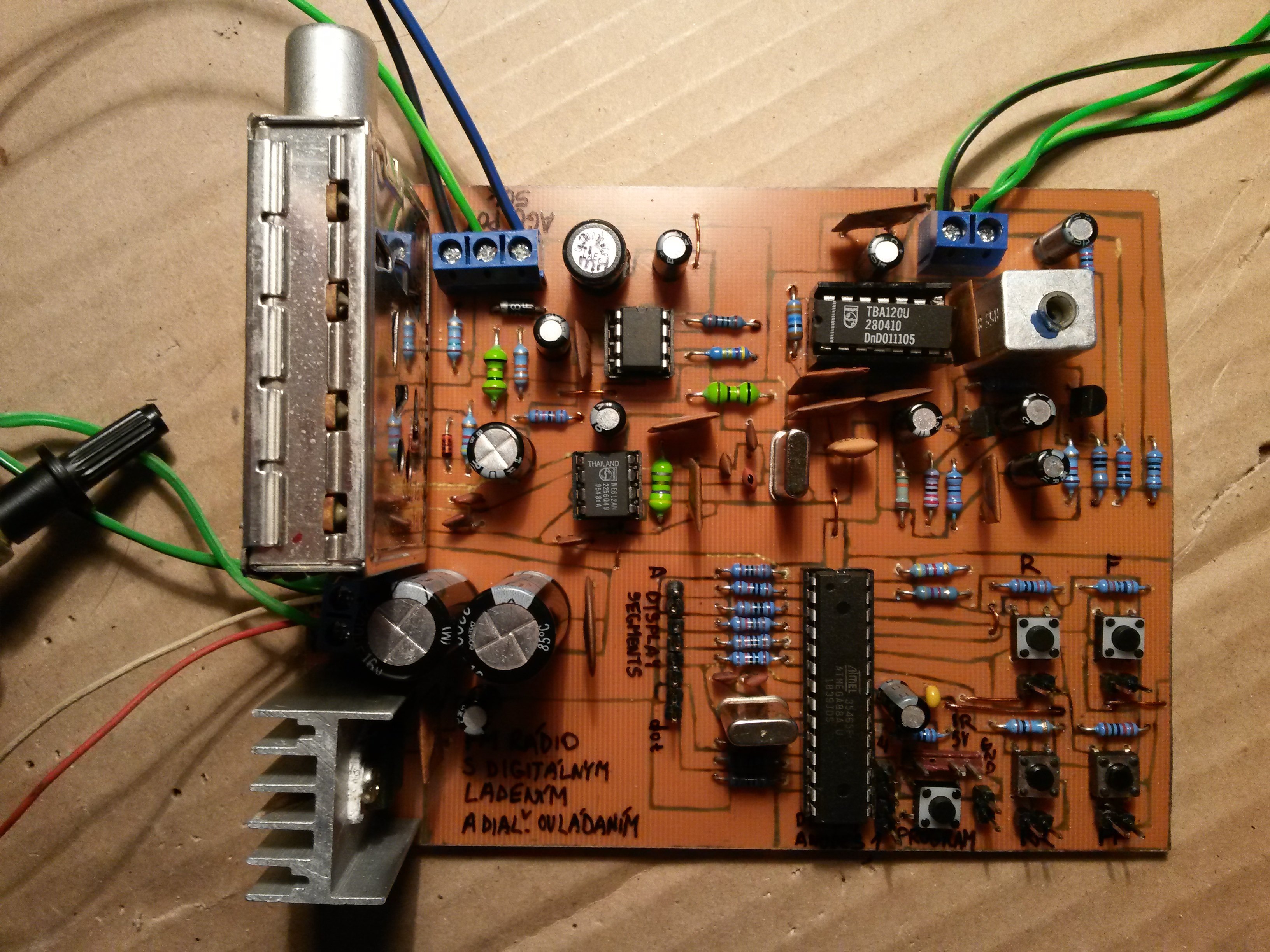
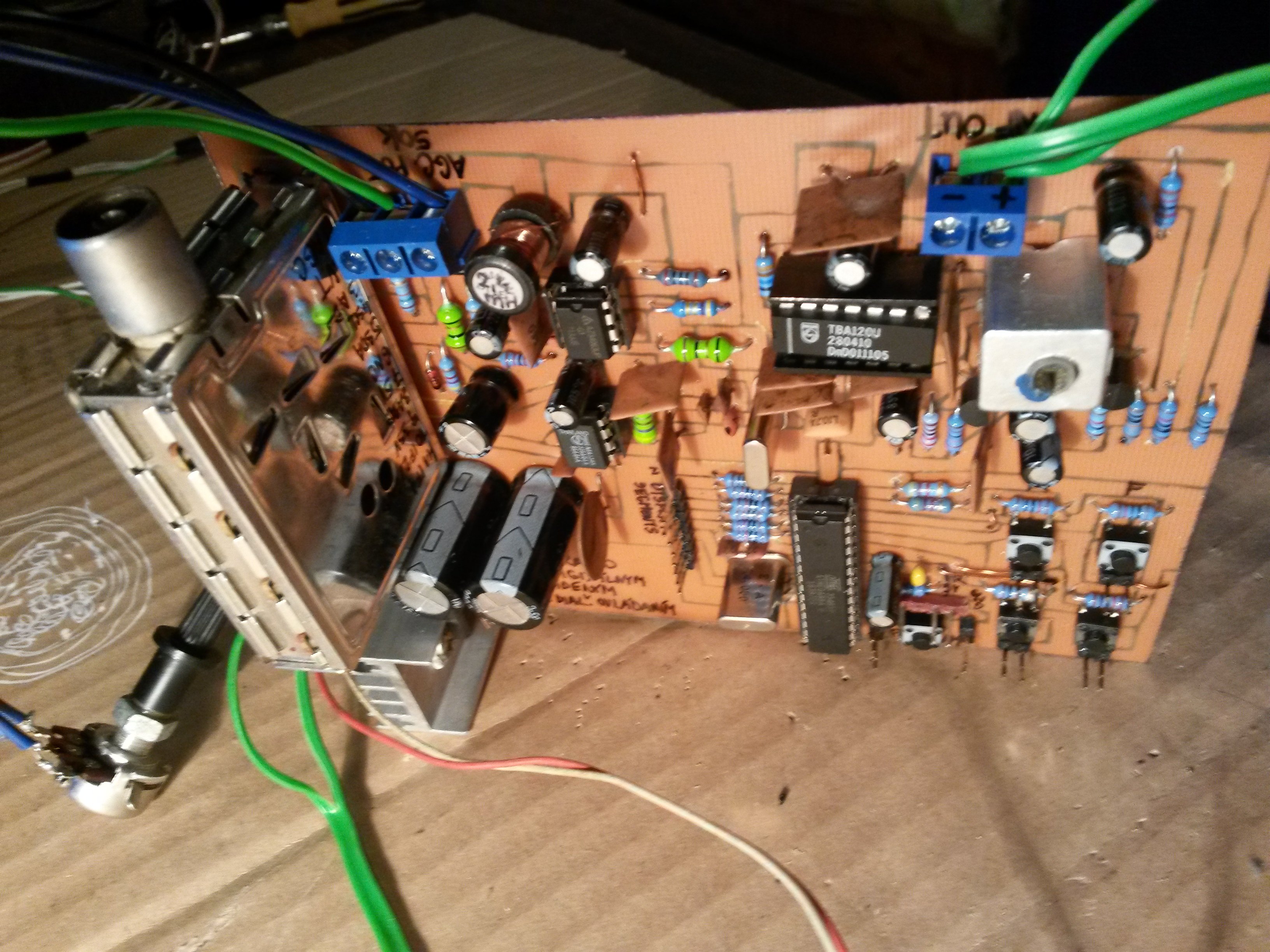
Some ICs in my project require 12V, so this voltage is used as supply voltage of the whole project. 5V is made from this voltage simply by 7805 regulator. And 33V is made using a DC converter with MC34063 (in reality it's around 42V, stabilized to 33V). Current consumption of whole project is around 200 mA.
Some TV tuners have symmetrical IF output (two IF pins), some have asymmetrical IF output (only 1 pin), mine has two. IF frequency is from 33 to 40 MHz. For further processing, IF frequency of 10.7 MHz was needed. That's why I used NE612 that is specially designed for this. It takes an input, mixes it with the frequency of local oscillator, and outputs a difference of these frequencies. I used a 48 MHz crystal in local oscillator, because 48 - 10.7 = 37.3 MHz. Wiring of NE612 is according to the datasheet, except the input. There are some inductors in the datasheet, which are not explained at all. But I found out that it works also when the input is only connected directly through a 1 nF capacitor.
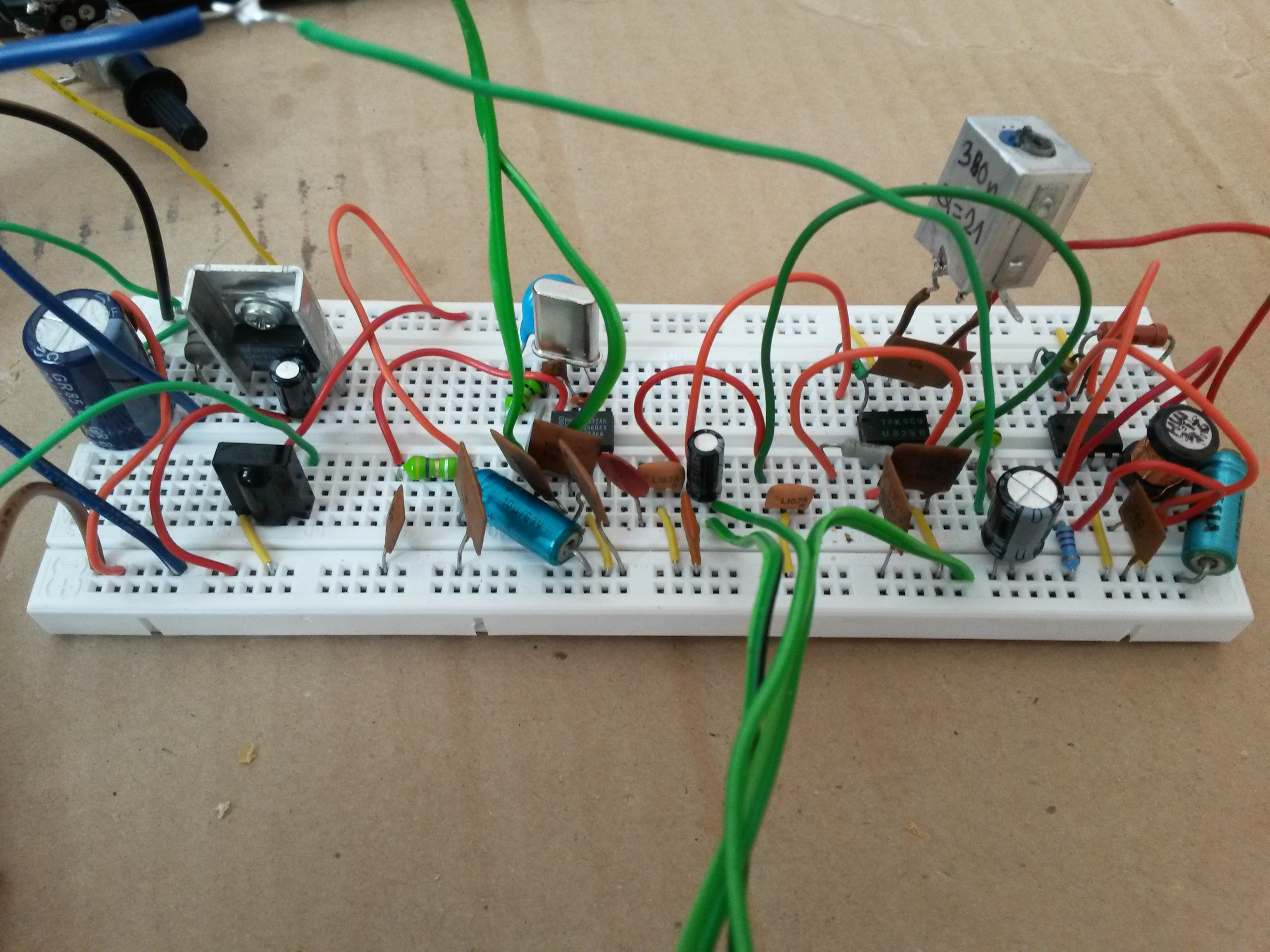
10.7 MHz output from NE612 is passed through a 10.7 MHz ceramic filter, and enters IF amplifier and FM demodulator in one chip, TBA120U, output from which is very weak, so I passed it into a simple amplifier with two transistors. Also different ICs can be used, for example A220D, A223D, K174УP1, or U829B, which do not require the amplifier, but then the schematic and PCB would have to be altered. But beware - TBA120T will not work.
The tuner is controlled by the Atmel ATmega88A microcontroller. It also cares about displaying the frequency, receiving IR codes, remembering saved frequencies, and other functions. The microcontroller is clocked by an 8 MHz crystal. I2C bus is abstracted by the i2cmaster library.
Fuses must be set like this: Extended: 0xF9, High: 0xD7, Low: 0xFF.
The receiver is controlled by 5 buttons:
- F: +0,05 MHz
- R: -0,05 MHz
- FF: +0,5 MHz
- RR: -0,5 MHz
- PROGRAM: remembers current frequency into one of the 10 memory slots. After pressing this button, "P?" appears, and it is possible to return back by pressing this button again, or remember current frequency by pressing one of the pre-programmed buttons on remote control.
The receiver can be used with any remote control. I used a library named IRMP and on first use, it is necessary to pre-program (learn) the buttons of remote control we are going to use.
Buttons F and R must be pressed simultaneously to enter the "IR code learning" mode. "P0?" is shown on the display, and at this point we have to press the button "0" on remote control that we will use to switch to frequency saved at zero-th position. After that, more IR codes are requested, up to P9. At the end, IR codes for F, FF, R and RR are requested. At this point, pre-programming of IR remote is done. We can tune in to some station, press button PROGRAM, and after "P?" is shown, we press one of the buttons P0 to P9 that we have pre-programmed before. This way, we can save stations for all 10 memory slots.
IR sensor can be of type TSOP1736, TSOP2236 or any equivalent salvaged from old TV.
If you decide to build this project, the steps of bringing it to life are the following:
- Check the PCB if there are no unintended shorts
- Instead of ICs use DIP housings, connect the AGC potentiometer, do not solder the tuner yet, do not connect the display and IR sensor yet
- Connect power source (12V) and measure:
- voltage on pin 7 of tuner (not soldered/connected yet) must be 5V
- voltage on pin 1 of tuner must be from 0 to 4V and must change when turning the AGC potentiometer (try both end positions)
- voltage between pins 4 and 6 of housing of MC34063 must be 12V
- voltage between pins 3 and 8 of housing of NE612 must be 5V
- voltage between pins 1/3/12 and 11 of housing of TBA120 must be 12V
- voltage between pins 7/20 and 8/22 of housing of ATmega88A must be 5V
- Disconnect power source and seat MC34063 into its housing
- Connect power source (12V)
- Measure voltage on pin 9 of tuner, it must be around 33V
- Disconnect power source and seat ATmega88A, connect the display and IR sensor (beware of cable orientation)
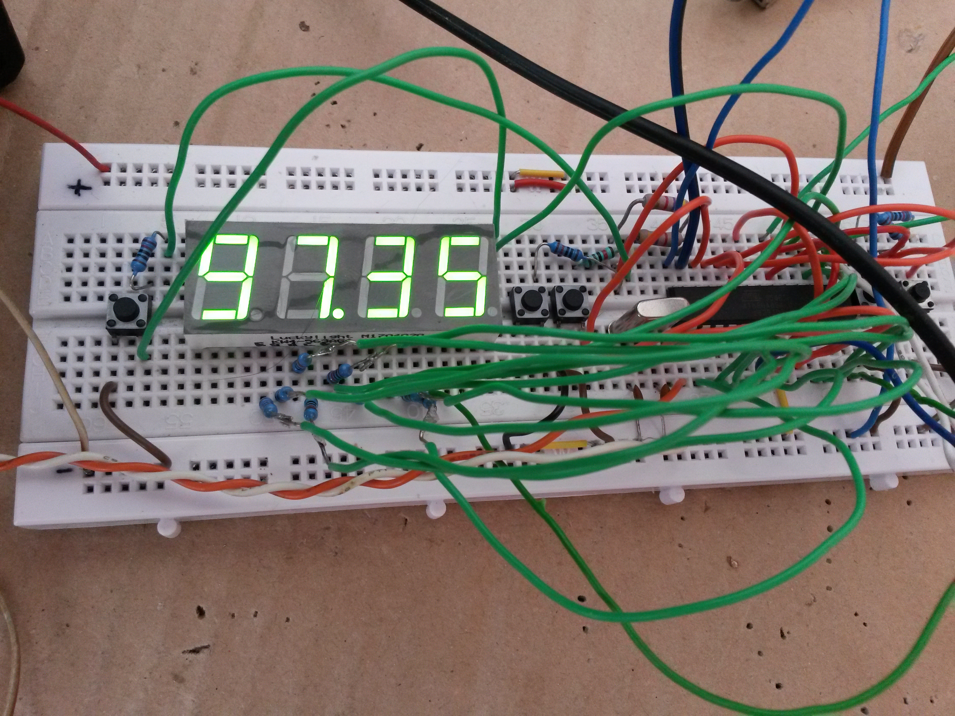
- Connect power source (12V) and check the display. It should show "87.50".
- Disconnect power source and solder the tuner
- Connect an antenna to tuner
- Connect power source (12V) and check current, should be at most 200 mA
- Disconnect power source and seat NE612 a TBA120 into their housings
- Connect headphones or audio amplifier in the output terminal block
- Connect power source (12V) and check current, should be at most 250 mA, most possibly around 200 mA
- You should hear white noise from the headphones or speakers. If not, try increasing volume. If still no noise, try adjusting the coil near TBA120. If still nothing, probably wrong inductor and capacitor are used for the TBA120 phasing LC circuit. Try changing them for values that should resonate near 10.7 MHz
- Tune on a frequency that you know a strong station broadcasts on
- Adjust the inductor near TBA120 into position with strongest volume and lowest distortion.
By the way, at every point, current consumption should not be more than 250 mA (use an adjustable lab power supply with voltage and current indication).
At this point, initial setup of the receiver is done. To calculate correct values of the LC phasing circuit, use this web page. An LC meter is very useful, and it should measure also low inductances below 1 uH, and also Q factor of inductors. The inductor you use should have Q around 40, but it also worked for me with inductor of Q = 2. You can either use a ready-made inductor, or salvage it from old TV / radio, where there should be the inductor with appropriate Q. There is also the option of winding your own (and use only the core from another inductor), but to achieve good Q, a hf cable should be used, that is not sold by anyone. Since I had a suitable inductor salvaged from old TV, I didn't try this.
If something goes wrong, an SDR receiver (that is connected to a PC via USB) is a really great companion. Of course, it must tune down to 0 Hz, or use an up-converter. With an SDR, you can check the IF output of the tuner (around 38 MHz even without an up-converter), and the 10.7 MHz IF also, directly on your computer screen. On the 10.7 MHz frequency you can see the tuned station, which moves left or right when you tune, fading away as it is filtered by the ceramic filter. But beware - you must connect the signal via a 1nF capacitor to the SDR antenna input.
In the zip file you can download on this page, you will find:
- datasheets of PLL tuners
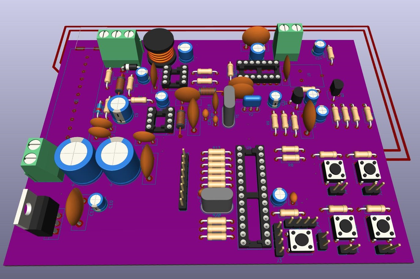
- KiCad project with schematic and PCB
- Atmel Studio project with software for ATmega88A
Quality of reception is good, and most importantly - the whole project contains only one variable LC circuit. All the "heavy lifting" is done by the TV tuner, which, as an industrial product, is 100% correctly tuned. However, after some time I realized that there are many "ghost stations" and noise, because of the lack of tuned circuits. It's the price we pay for circuit simplicity.
If you have some question or problem, don't hesitate to ask. You can use the comments form on this page.
I learned so much and really enjoyed experimenting while building this project. And, there comes the great aspect - I gave new life to a component from old TV that would otherwise end on a junkyard.
Update 9th December 2019: By fiddling with various other radios, I found out that the TBA120U has an unregulated AF output on pin 12, whereas a regulated AF output on pin 8. Originally, pin 8 was used in this construction, and pin 12 was connected to GND. This is now fixed both in the schematic and in the KiCad project in the package for download. Also I removed the deemphasis capacitor on the AF output because its presence caused that eventually connected stereo-decoder was not working.
")