Ecological FM receiver with components from TV Tesla
The article starts below the video.
I named this receiver an "ecological" one because components can be easily obtained for free by dismantling old equipment, namely Tesla TVs.
Parameters:
- voltage: 12V / 100mA
- frequency range: 88 - 108 MHz
- architecture: superhet with double mixing
- output: AF for headphones or audio amplifier
- tuning: manual, best with multi-turn potentiometer
- AGC: manual (most stations play well with maximum AGC, but some play better with AGC in the half)
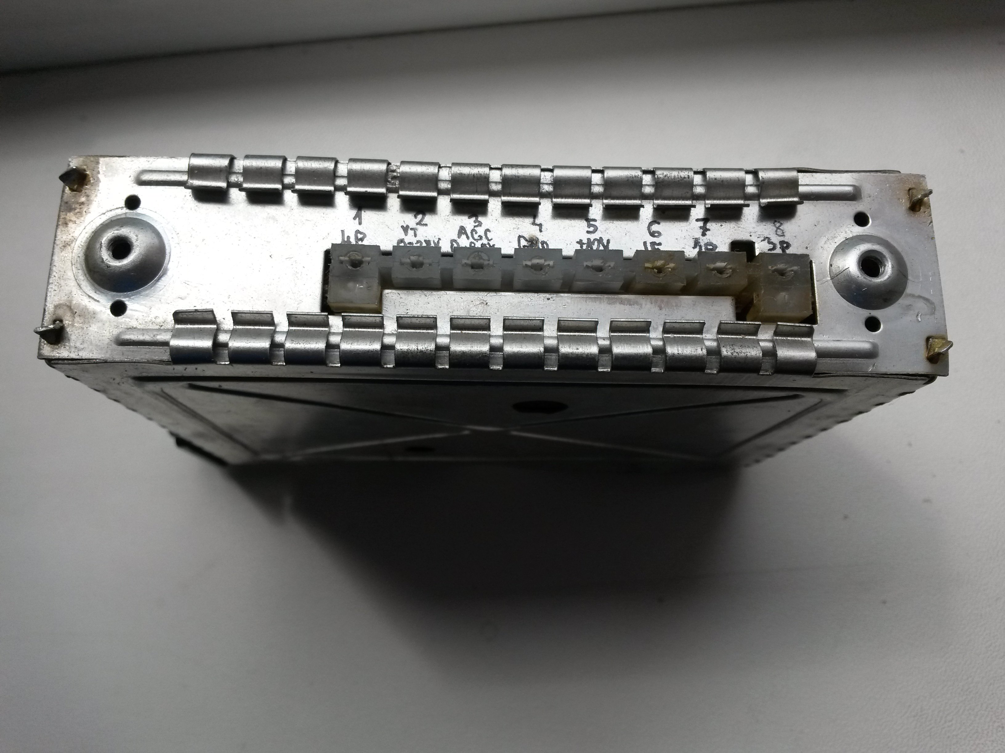
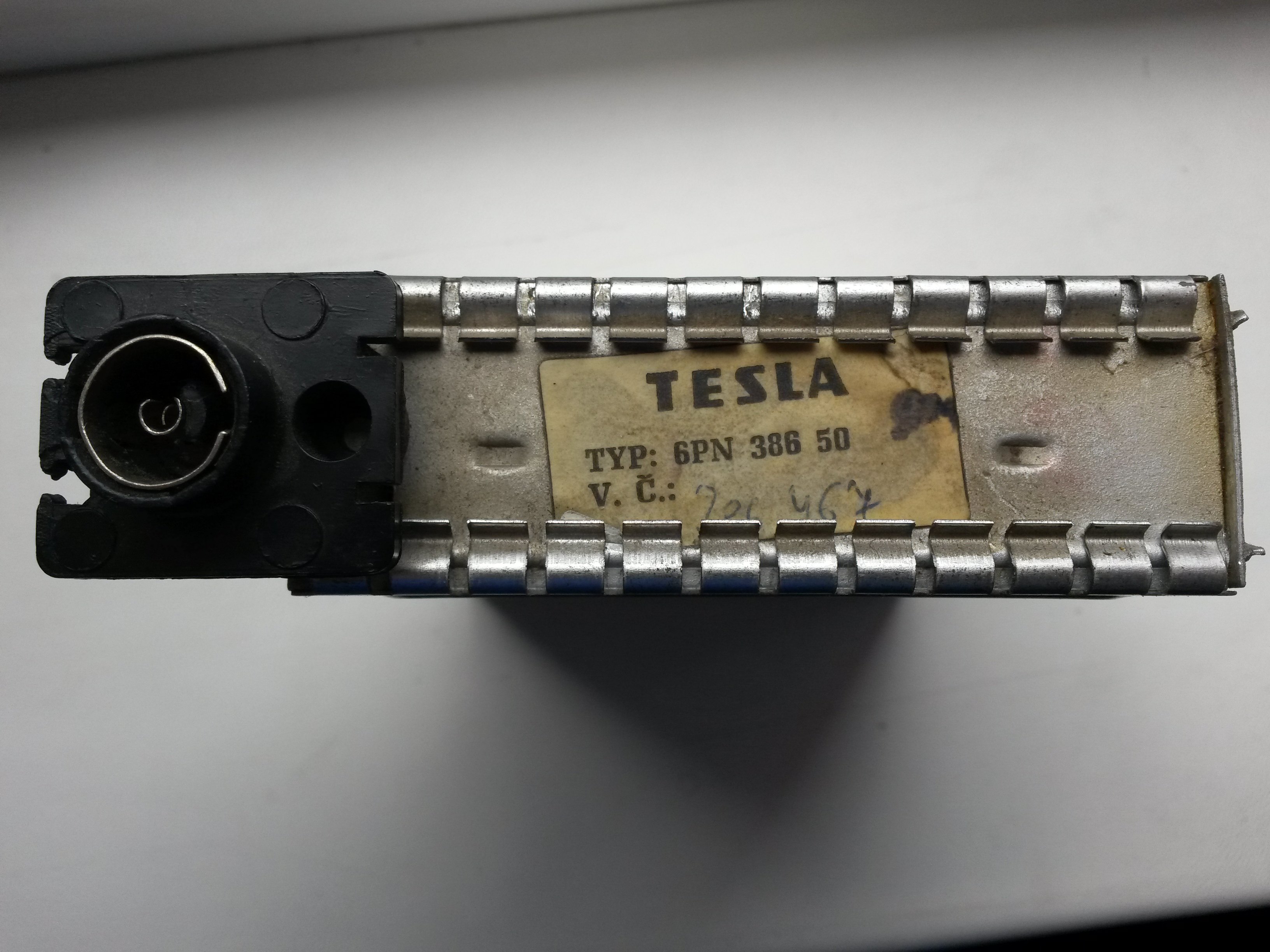
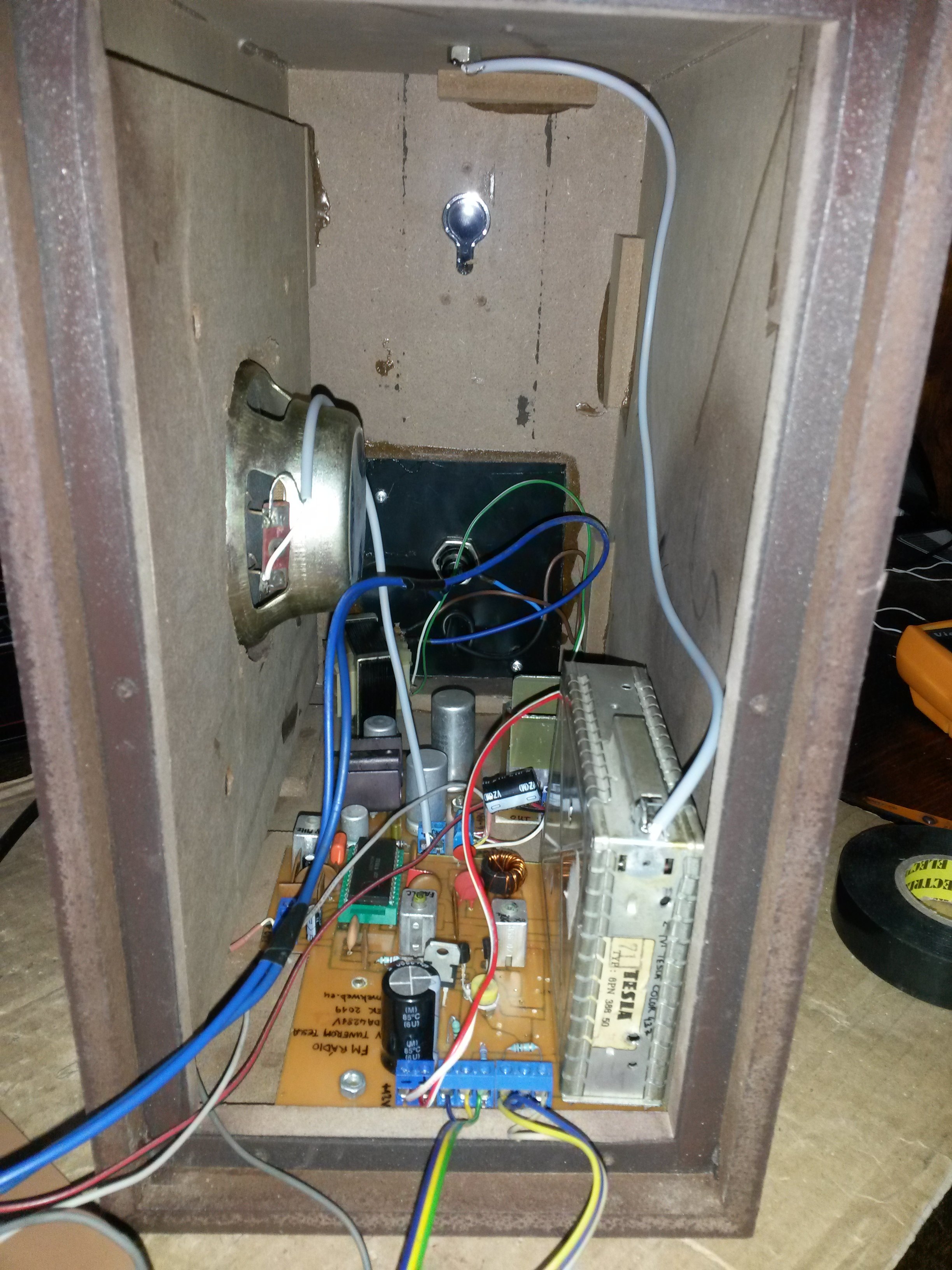
Many distinct kinds of tuners were used in Tesla TVs, and this construction is built around tuner marked 6PN 386 50. This tuner has no pins, only holes, as it's a module that has pins soldered on the PCB, which makes switching tuners very easy if needed. You can see how this tuner looks like in the pictures below.
Another important component is IC MDA4281V, which is a "quasi-split sound circuit" in Tesla TVs. AFAIK, I am the only one in the world who tried to re-use this IC to receive FM broadcast (because I found nothing on the internet, except the datasheet, TV schematics and e-shops).
MDA4281V processes the IF from tuner directly (38 MHz), so we don't need the harder-to-obtain mixer IC NE612. A big advantage of this IC is that it contains a mixer, oscillator, IF amplifier, FM detector and demodulator, all in one plastic case, and it outputs AF signal directly. However, there is also a disadvantage - input IF signal must contain picture carrier at 38 MHz, but today we have none anymore. That's why there is an auxiliary LC oscillator that adds this signal into the input and fakes the picture carrier to fool the MDA4281V.
The circuit contains three tuned circuits. Tunable inductors can be salvaged from old TVs as well - don't throw them away. To build this construction, however, some more special equipment is required, that not every amateur has at home. But this equipment is very, very useful, not only for this construction.
- a quality LCR meter that can measure also in the nH range, I recommend DER EE DE-5000
- SDR receiver for PC USB port (plus eventually up-converter to receive signals lower than 50 MHz) - it's basically a very cheap spectrum analyzer, without which tuning of the auxiliary oscillator is impossible
Here goes the schematic:
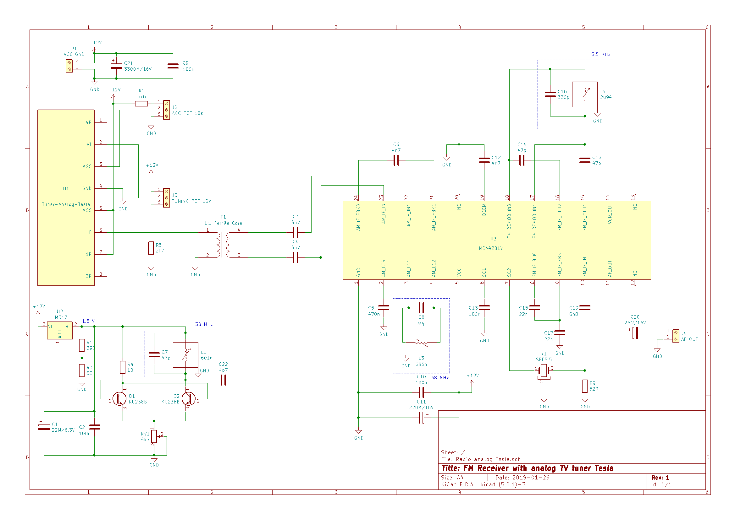
Tuner is connected identically as for other tuners that use manual tuning - I already published detailed description in the article about tuners with manual tuning and so I won't reiterate it here. Tuning is limited from the bottom by a 2k7 resistor, which "trims" part of the lower band where there are no stations anyway, and it makes tuning of the rest of band a bit more precious.
But beware - the tuner cannot be used "as is". It needs to be re-tuned. That's because normally it only tunes until 103 MHz on 1st program, but what's worse, to tune FM broadcast stations, higher voltage is needed (up to 30V). By re-tuning the tuner, we gain access to the whole FM broadcast band until 108 MHz, and move the whole band much lower, so that the FM broadcast band is in the lower part of 1st program, and full 12V tuning voltage corresponds to a frequency somewhere near 108 Mhz. This way we don't have to use a DC converter to get 30V. I tried it also with the DC converter, but it added too much noise, even with optional output LC filter.
Fortunately, re-tuning the tuner is fairly easy. Only a single inductor needs to be stretched - it's marked by the arrows in the picture below. It's best to connect 12V tuning voltage to the VT pin, connect IF from tuner to SDR and in PC watch when the FM station with highest frequency appears in the spectrum (32 - 40 Mhz). In Žilina in 2019, that is Jemné melódie 106,9 Mhz. Since we want to lower required tuning voltage as well, the inductor must be stretched pretty extensively.
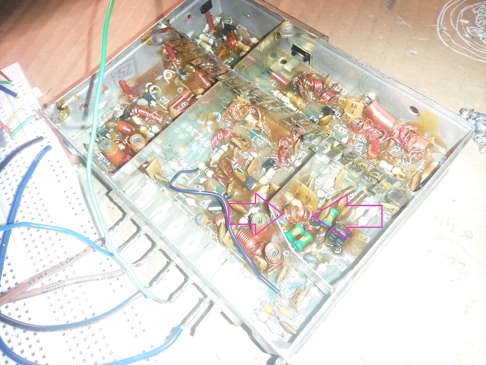
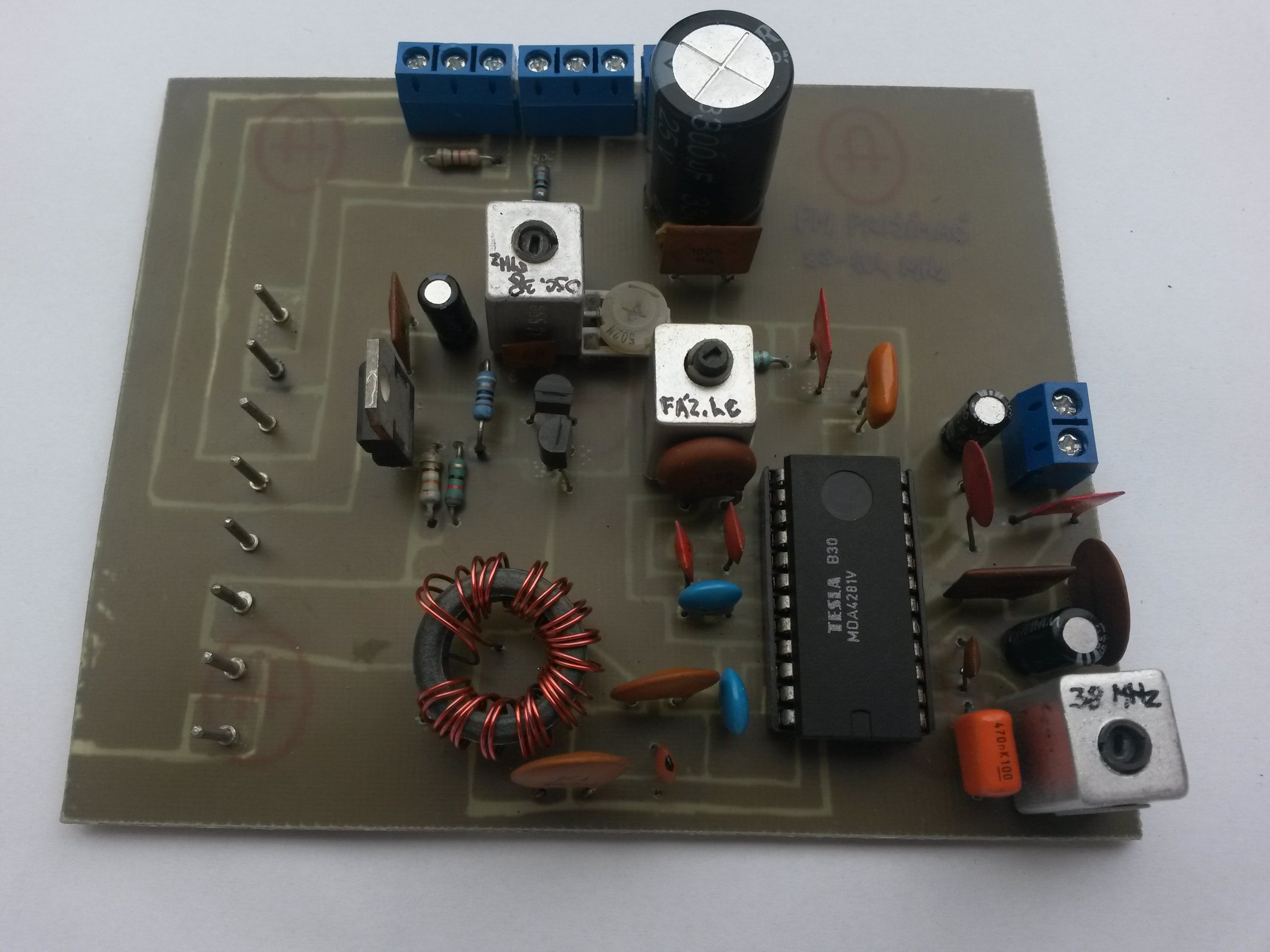
IF output from tuner is asymmetrical, but MDA4281V requires a symmetrical input. For this reason, there is a 1:1 balun on ferrite core. It can be any small toroid that you happen to have at hand, maybe from old TV or monitor. Wire diameter or number of turns is not really important. It must only have identical number of turns on both primary and secondary sides, wound bifilarly. Number of turns should be enough to cover at least 5/8 of toroid's perimeter. The turns don't need to be next to each other. Look at the pictures below (where finished PCB is picured) to get an idea.
Auxiliary 38 MHz signal is mixed into one of the symmetrical inputs to fool the MDA4281V (see description above).
The rest of the circuit is partly according to datasheet, but there were some errors in the datasheet too, and some components had different values. There is also a 5.5 MHz ceramic filter instead of phasing LC circuit. But I got very bad results with it (distorted reception) and it couldn't be tuned to get better reception. That's why I used a classic phasing LC circuit that can be fine-tuned. I found out how to connect it from Tesla TV schematics.
Output of sound carrier is present on both pins 6 and 7 but we need only one, the other one is grounded via a 100n capacitor. Sound carrier is passed through a ceramic filter into the input of FM demodulator. This one is fine-tuned using the aforementioned LC circuit on pins 15 to 18.
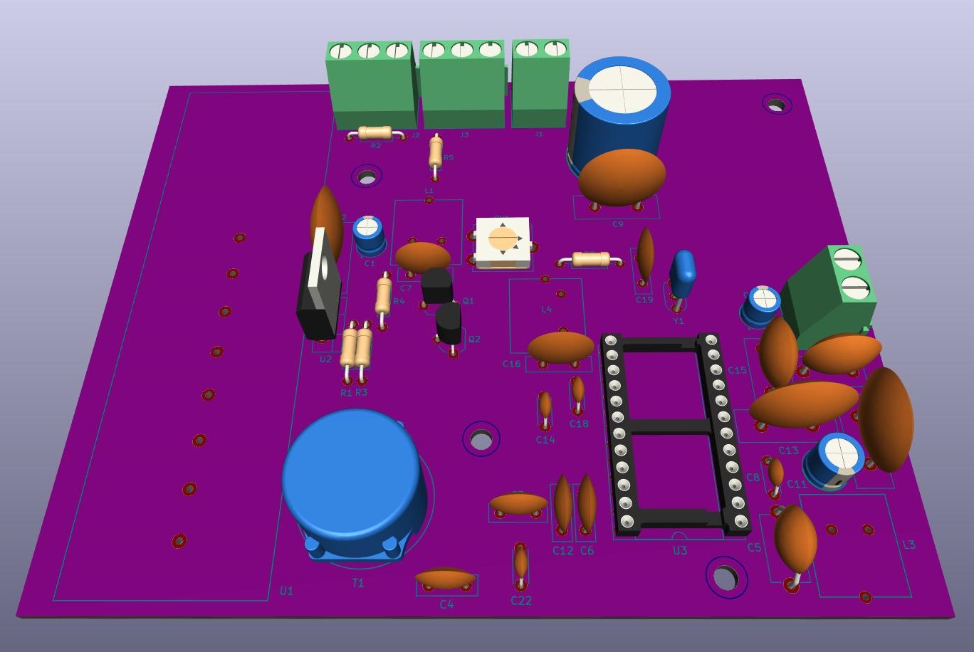
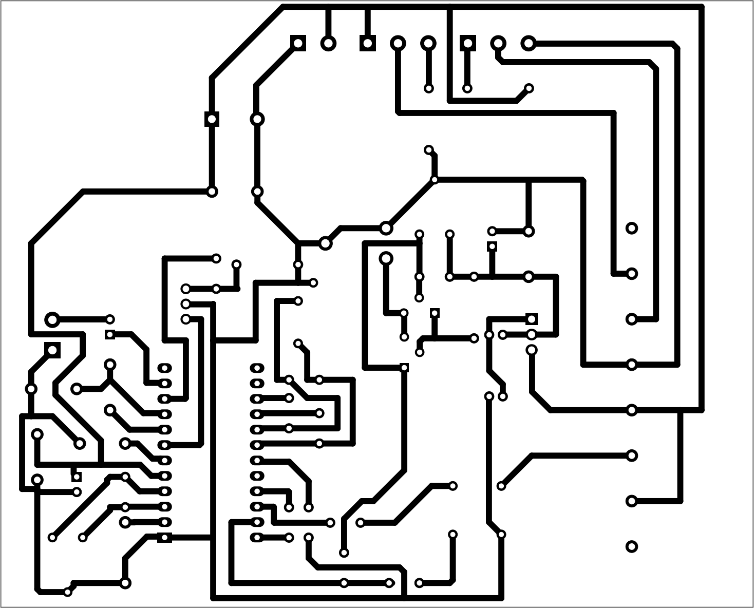
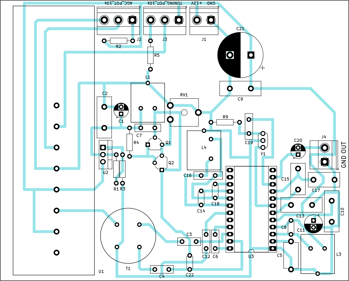
You can find the whole KiCad project with schematics and PCB in the zip file downloaded from this page. For those who don't have KiCad, I am publishing the PCB as well as the deployment plan. Note: tuner reaches beyond boundary of the PCB. It's to spare some material and to not overflow the 10 cm boundary which is a standard when you buy a low-cost copper laminate. 10 cm is vertical dimension of the PCB.
After deployment of components, follow these steps:
- disconnect the tuner (there are only pins on the PCB)
- disconnect MDA4281V (there is only a socket on the PCB)
- connect input voltage and both potentiometers
- measure voltages: - middle pin of LM317: 1,5V - pin 4P of tuner: 0V - pin VT of tuner: 2-12V (depending on Tuning potentiometer) - pin AGC of tuner - 0-6,5V (depending on AGC potentiometer) - pin VCC of tuner: 12V, pin 1P of tuner: 12V, pin 3P of tuner: 0V - voltage between pins 1 and 5 of socket for MDA4281V: 12V
- disconnect input voltage
- connect SDR on pin 23 of socket for MDA4281V (important: set RF Gain on SDR to some higher value, e.g. 40 dB)
- connect input voltage
- using SDR, tune to 38 MHz and by turning the RV1 potentiometer, get highest peak somewhere near 38 MHz, then by turning the core of inductor L1 fine-tune this peak exactly to 38 Mhz
- disconnect input voltage
- connect the tuner
- seat MDA4281V in its socket
- connect SDR on pin 7 of MDA4281V
- connect input voltage
- using SDR, tune to 5.5 MHz
- turn AGC potentiometer to the fullest (to get maximum AGC voltage) and turn Tuning potentiometer - there should be some FM stations appearing on the 5.5 MHz frequency. If not, connect SDR to IF pin of tuner and check if the stations are there in the 32 - 40 Mhz band (to verify that tuner itself is OK)
- tune some stronger station on the 5.5 MHz frequency and turn the core of inductor L3 to get maximum peak
- disconnect SDR (important: with SDR connected, stations are with noise, but crystal clear without SDR)
- connect headphones
- by Tuning potentiometer, tune some station the best it can get (maybe there will be only noise, or maybe it will be distorted, that's OK for now)
- by turning the core of inductor L4, tune the IF of 5.5 Mhz (phasing circuit) so that in the headphones the station is without distortion and as loudest as possible at the same time
If only some few strong stations can be tuned, maybe you need to experiment more by turning core of inductor L3, and turning the tuning and AGC potentiometers. I only had trouble with a weaker station that could only be received with L3 in some very exact position.
This article describes only the module of FM receiver. Headphones or an audio amplifier with speaker can be connected to its output. Or maybe connect a stereo decoder first, and then stereo amplifier with two speakers. An RDS decoder should work as well.
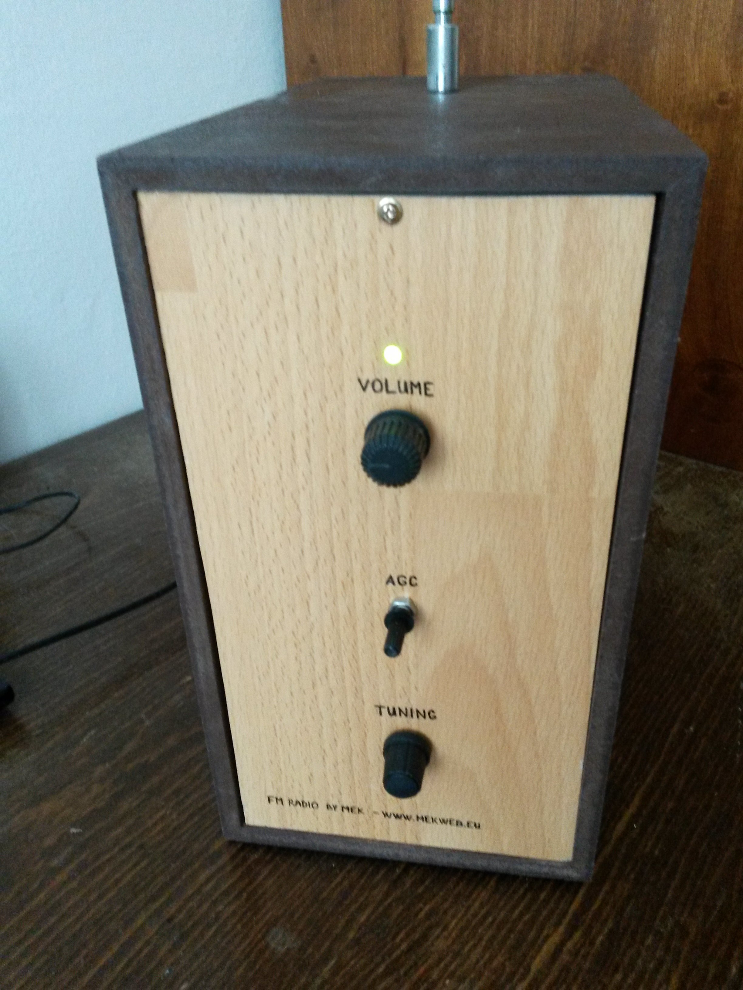
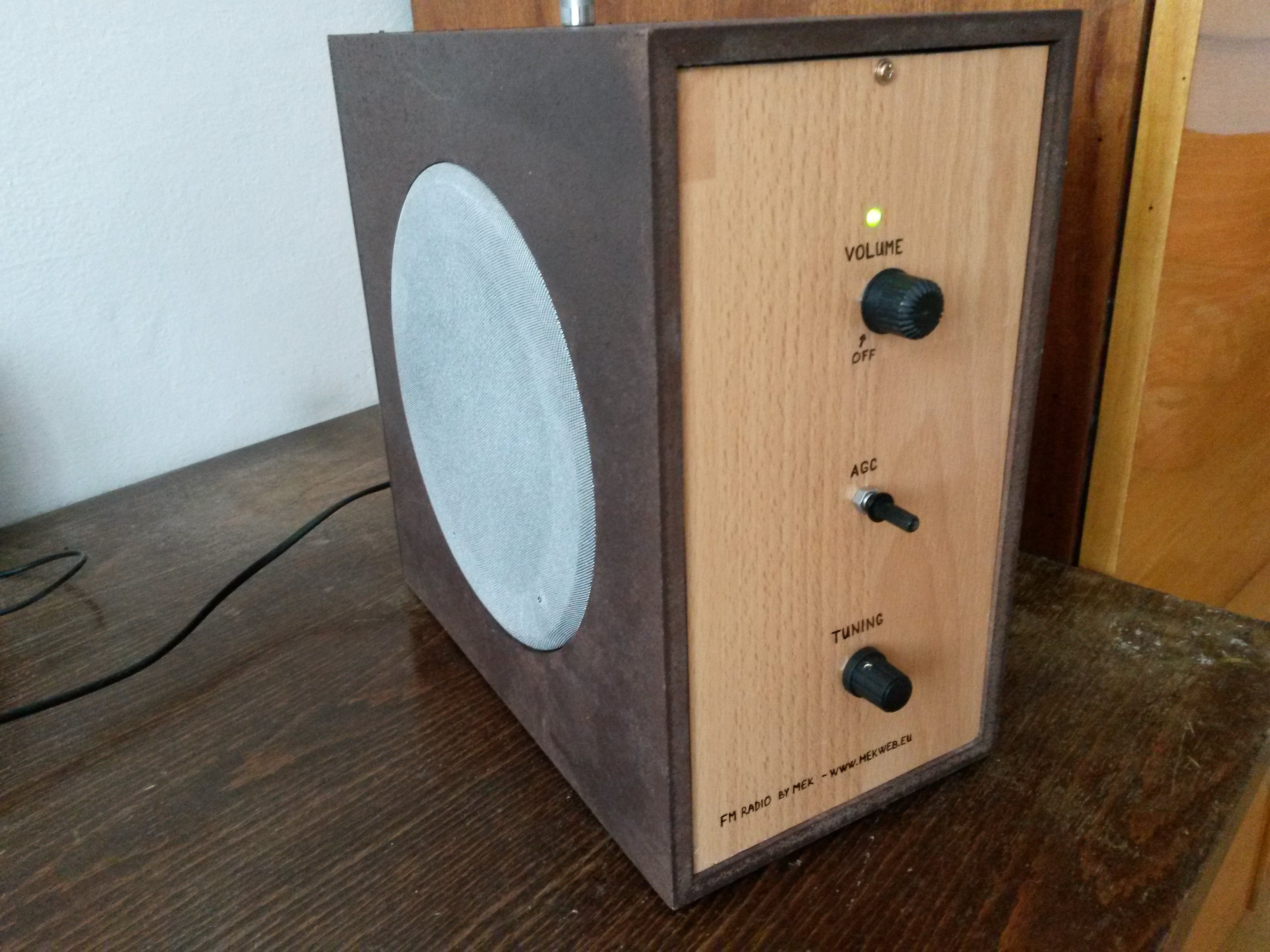
I used a small transformer connected to mains, then rectified the lowered voltage and stabilized it using voltage stabilizer MA7812 (also from production of Tesla) so I got 12V. I used a fuse on the primary side of transformer (T 63 mA), and another fuse on the secondary side (T 800 mA - weaker one got burned by inrush current surge when turning on and the large capacitors were charged). With maximum volume, current on primary side is 40 mA and on secondary 300 mA. I connected a mono audio amplifier to the output of FM receiver. The amplifier was built around IC К174УН7 (Russian copy of TBA810) and a speaker. Since I mounted all stuff into a case from old subwoofer (which I sprayed brown), I re-used existing opening in the case and so the receiver is mono. I don't remember where exactly I got appropriate speaker with correct mounting holes and correct diameter, possibly also from some old TV. I always put the speakers aside, one never knows when they come in handy. The sound of the receiver is much better than I thought. As it always is, more work was a non-electrical one which I don't enjoy as much - customization of the subwoofer box: sawing, drilling, mounting, glueing...
Beside PCB terminal blocks and copper laminate for PCBs, I didn't need to buy anything, and so this construction almost did not cost me anything (well, apart from a lot of time). But I don't know why, some stations cannot be received at all, maybe the signal is too weak. But other, stronger stations, are present also on frequencies they don't broadcast on. Maybe that is the price of simplicity of this circuit, but I don't care that much.
If you want to build this construction and encounter a problem, I will be happy to give advice in the comments below this article.