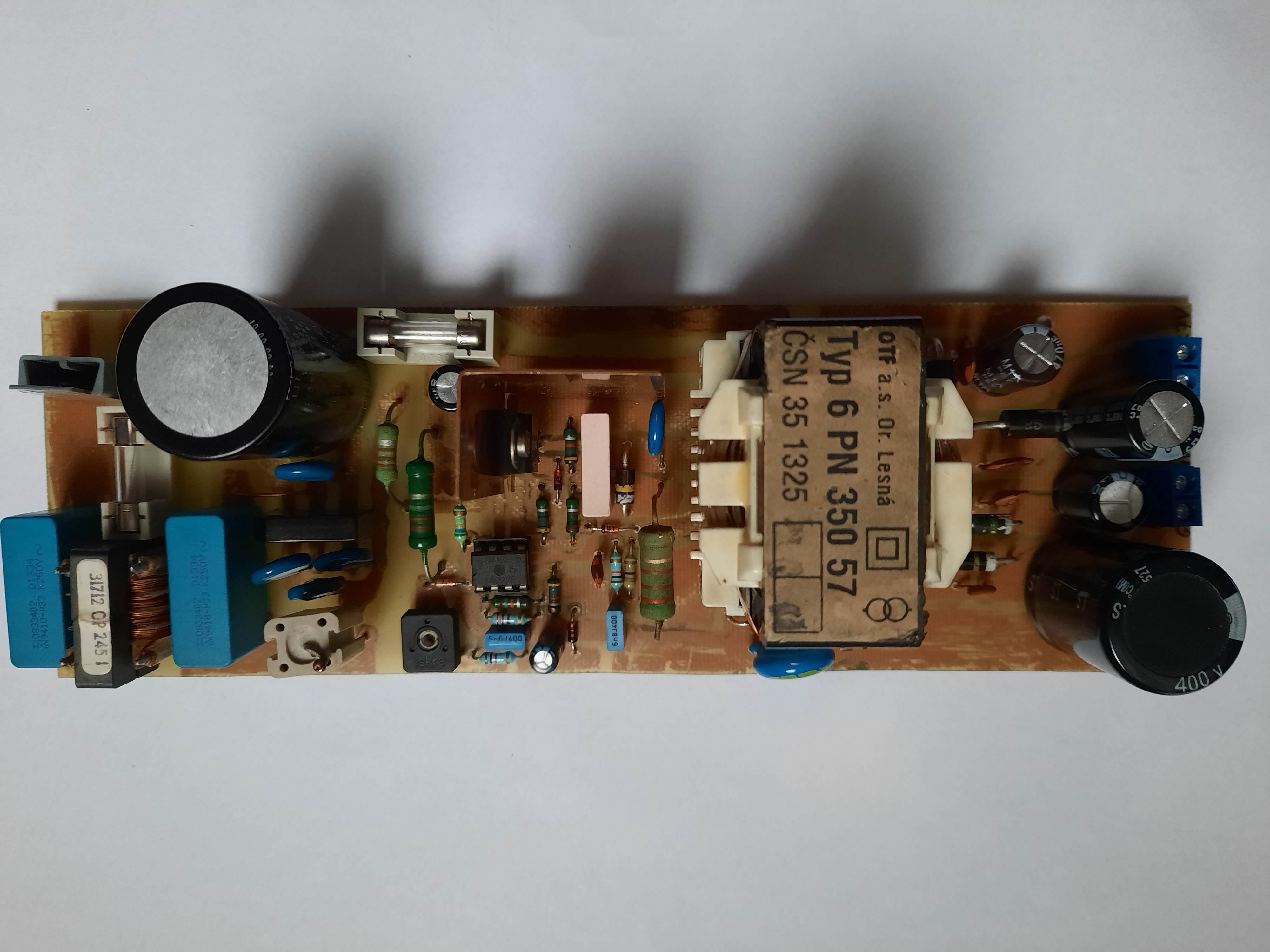
Switch-mode power supply from CRT TV with transformer 6PN 350 57
While taking apart a CRT TV I thought of how the impulse transformer could be re-used. To this time I thought that impulse transformers were a one-of-a-kind component that is tailor-made for only one specific circuit and could not be re-used. However, a quick look into the schematic of the TV revealed that it could be in fact re-used pretty easily as the power supply is pretty much a discrete block in the schematic. I like to take apart old electronics and use the components to make something usable again, so why not try it.
Unfortunately, a google search of transformer type - 6PN 350 57 - yielded no useful results. That's typical for impulse transformers - no documentation whatsoever. So I didn't know what voltages and currents it can output.
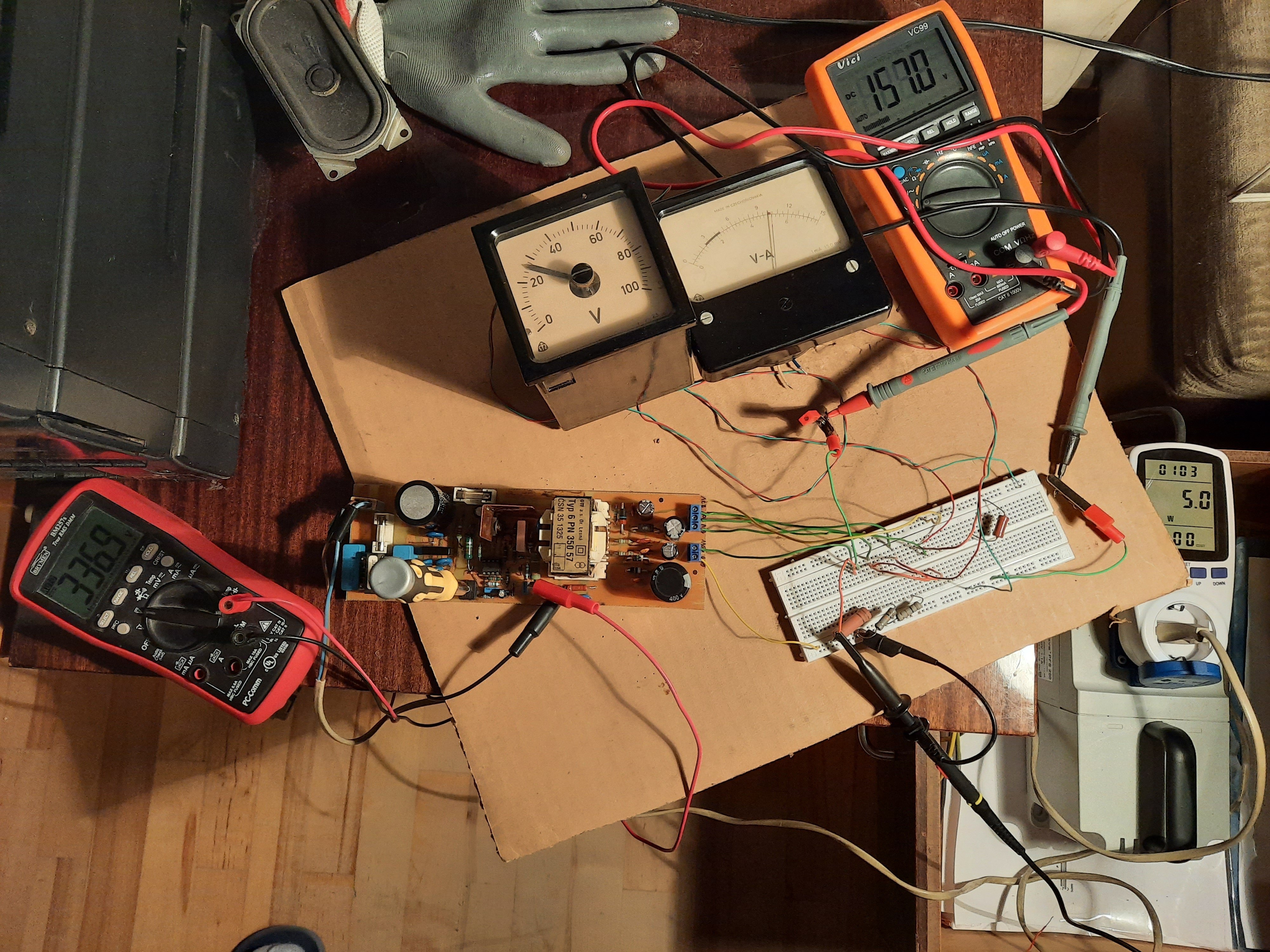
I had to find out this information my way. Doing it on a breadboard wouldn't be a good idea because it make the SMPS behave unpredictably, and there are also high voltages. So I drew a schematic and PCB in KiCad. Then I made some measurements and adjusted the schematic and PCB. The results are described on this page. The archive for download contains the KiCad project - schematic and PCB - and there are also some photos included.
Power supply has the following voltages on its outputs. Apart from voltage 4 (which is too high) they are tested on a dummy load. I also watched input power from mains (using a wattmeter).
- 27 V without load / 23.5 V 0.2 A / 20 V 0.5 A / 18 V 0.7 A max. (power supply turns off on 0.8 A) - input power for max. load: 25 W
- 19 V without load / 16.5 V 0.2 A / 15 V 0.5 A / 12.5 V 1 A / 12 V 1.1 A max. (power supply turns off on 1.2 A) - input power for max. load: 25 W
- 10.5 V without load / 7.9 V 0.2 A / 6.5 V 0.4 A max. (power supply turns off on 0.5 A) - input power for max. load: 12 W
- 160 V without load / 131 V 60 mA / 130 V 90 mA 18 W / 130 V 130 mA 24 W / 129 V 172 mA 30 W / 127 V 300 mA 48 W / 126 V 380 mA 60 W / 126 V 450 mA 70 W - output loaded with light bulbs from microwave ovens connected in parallel. For maximum load, there were 7 light bulbs connected.
BEWARE - first voltage has its own ground (marked GND1), that is different from other grounds (GND).
Potentiometer RV101 can be used to adjust all output voltages at once. In CRT TVs it was used to set correct voltage for the CRT - more models of CRTs could be used from different manufacturers.
When 4th output is maximally loaded (see above), voltage could be adjusted from 98 V to 153 V. Power draw from mains was then 47 W to 95 W.
This power supply surprised me with the power on the 4th output (HV), while it didn't even sweat noticeably. On the other hand, the pretty low maximum load of the other voltages was a bit disappointing. That could possibly be solved by rewinding the windings with wire of larger diameter.
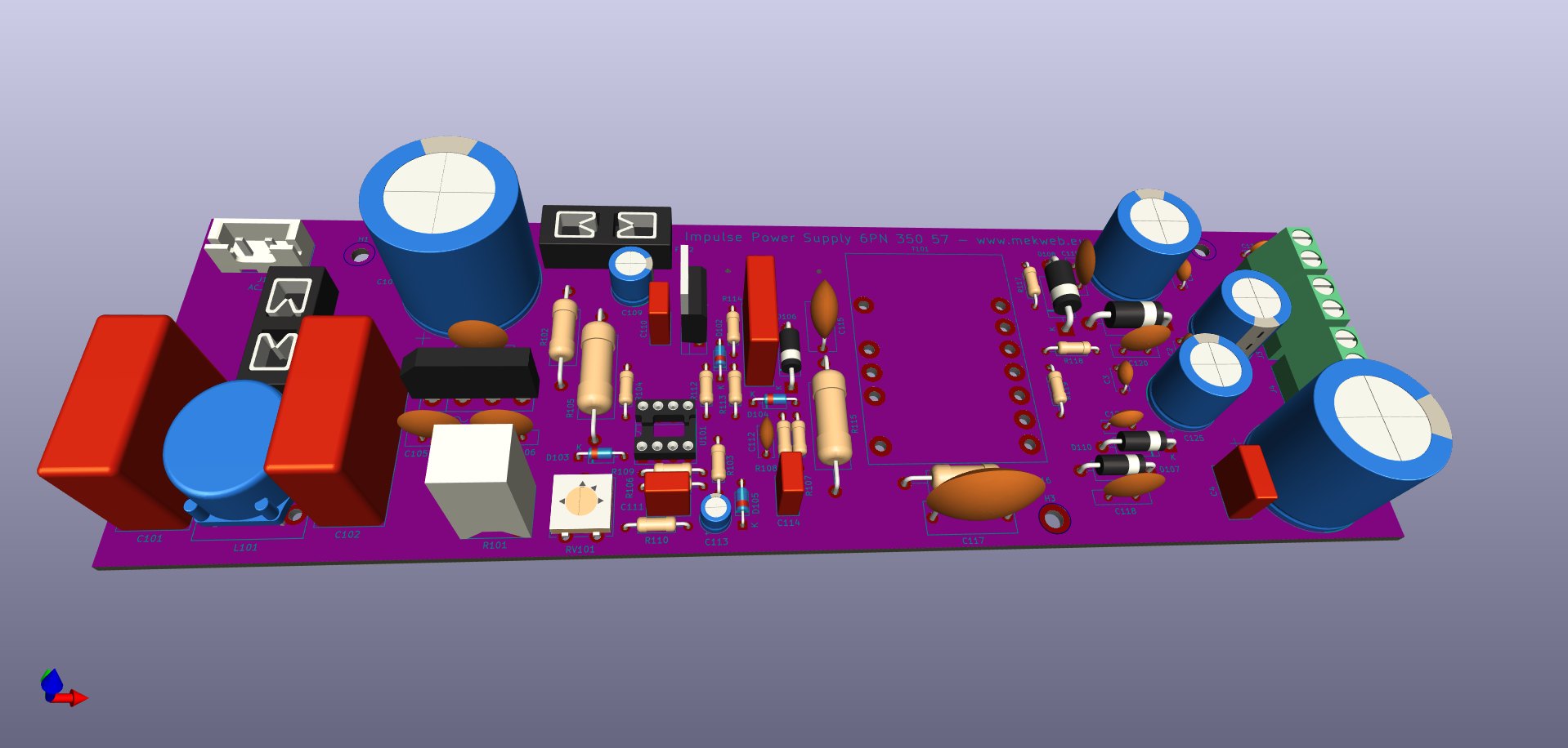
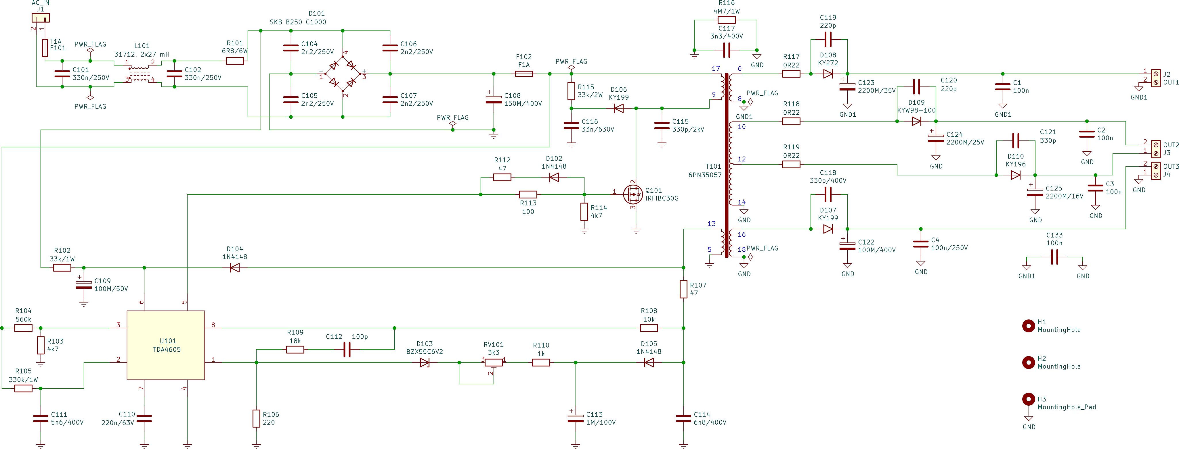
Below is the latest schematic (parts are annotated the same way as in OTF TV):
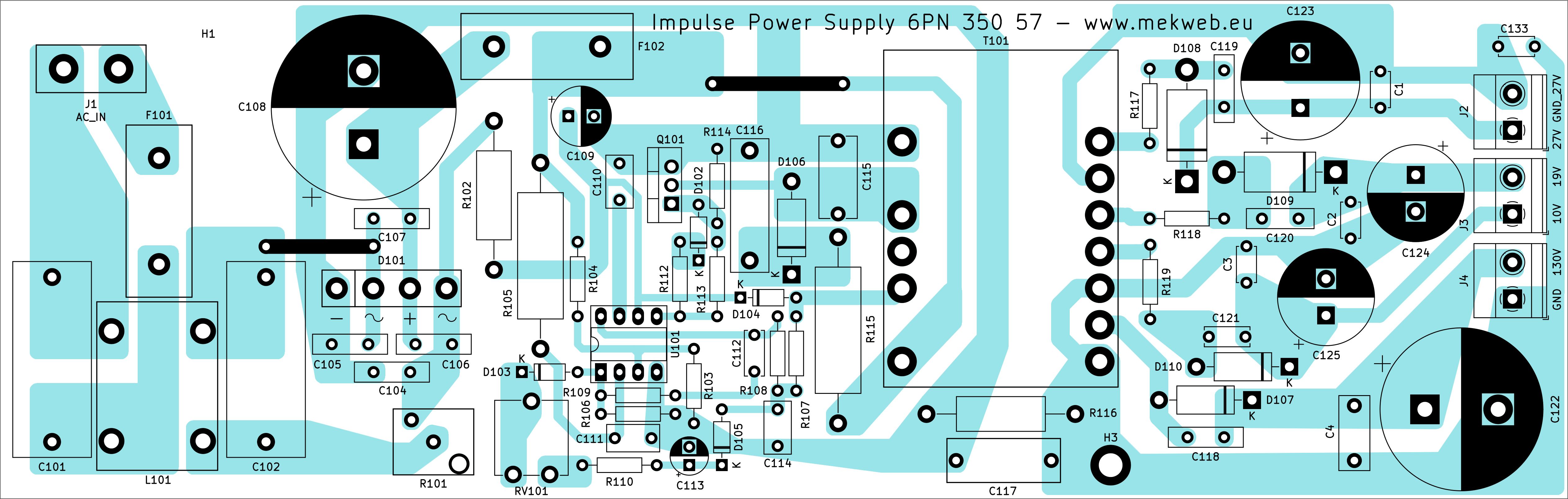
And the PCB - size is 214 x 68 mm. There are 3 holes for eventual mounting screws.

By taking measurements on my oscilloscope, I found out that all voltages are OK without load, however, when loaded, there were significant spikes and ripple of random frequencies (pk-pk to 1.5 V). This can be solved by loading the HV output with a 15k / 5 W resistor, so current will be 9.1 mA (according to my measurement). The resistor will be a little hot but not much. The low voltage outputs must use additional 1000 μF capacitors, but those are normally already present on an eventually connected board. Then, the voltages are nicely straight without ripple.
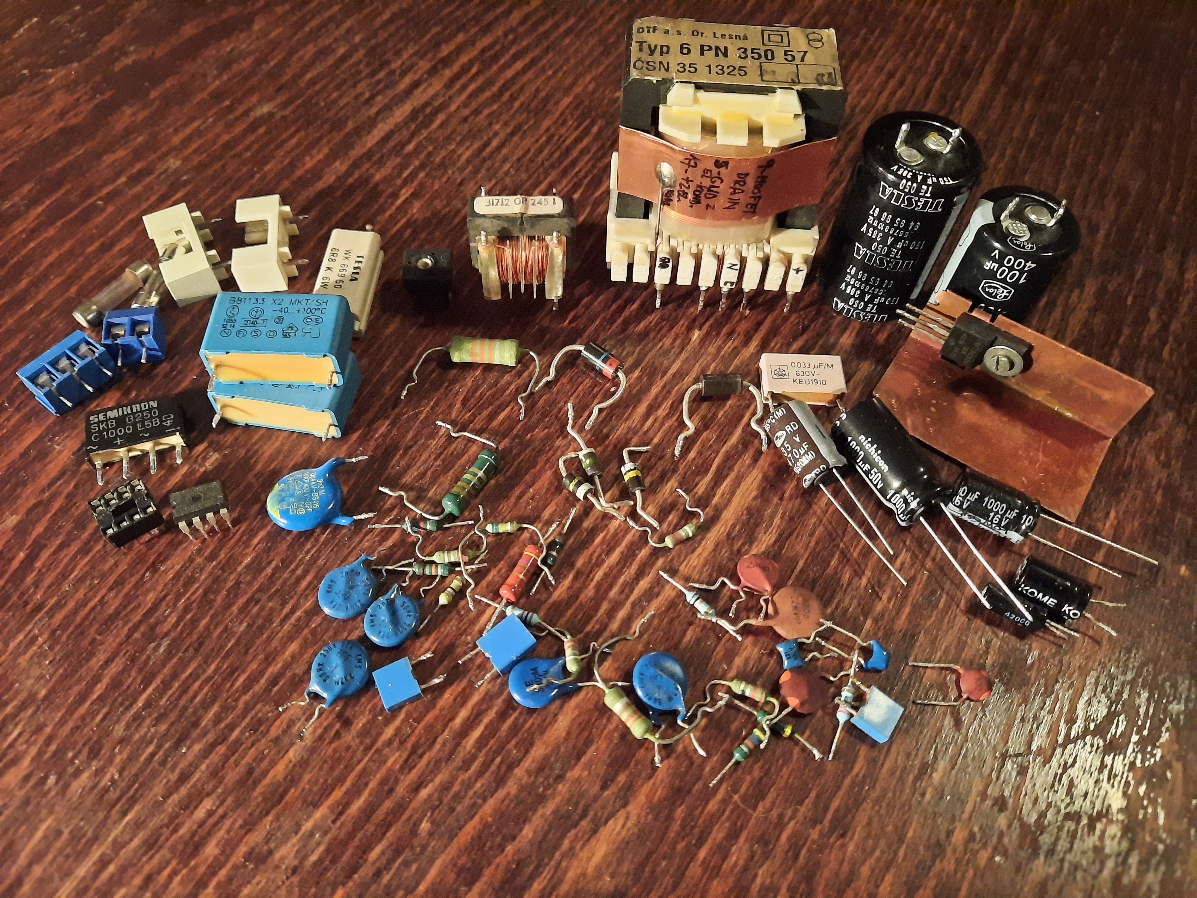
All required components can be salvaged for free by taking apart an OTF Orava CRT TV. So the only cost is in material and time (which I don't count, since it's a hobby :) ).
In the place of the MOSFET transistor, also a BUZ90A was used sometimes in this type of TVs, and maybe some others, that should also work with this circuit. Also, take note of the types of components (especially their maximum voltage) and use the same kind of components as were originally in the TV. For example use a ceramic capacitor where there was a ceramic capacitor, use MKT/MKP where MKT/MKP was and so on. Before turning the power supply on the first time, set up RV101 for 1k3 resistance (as it was in the TV).
Also a few words of warning: This circuit requires manipulation with dangerous mains voltage. Use an isolation transformer and isolation gloves. Never touch the power supply when connected to mains and before any manipulation make sure that capacitors C108 and C122 are discharged - they can hold their charge even after some time when disconnected from mains.
The author takes no responsibility for any damage done when building this circuit. You do everything on your own reponsibility.