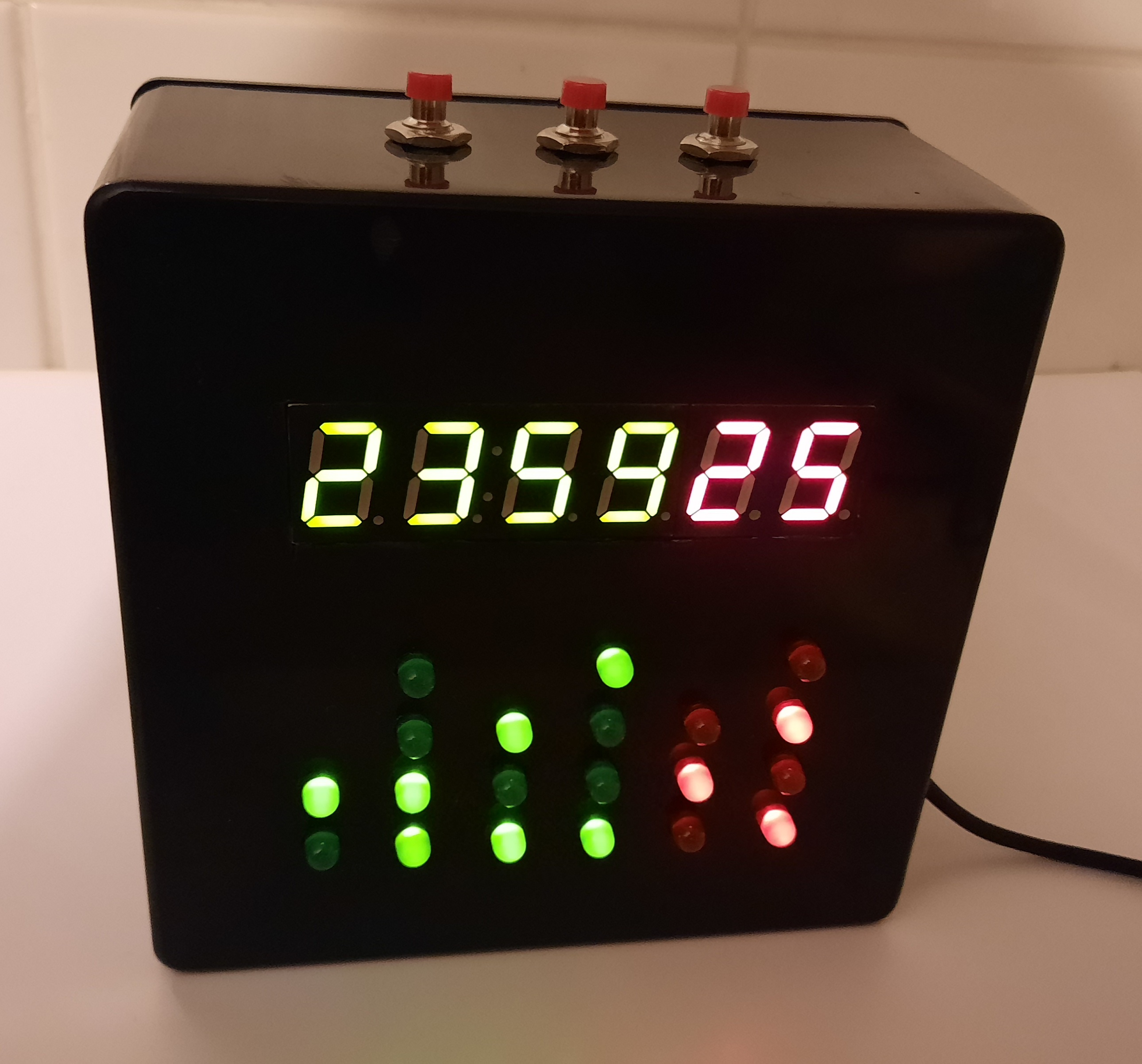
Digital-binary clock
The article starts below the video. In the video you can see an earlier version of this clock, which was set up by 4 buttons that changed the speed of the clock. In this article, the clock are set up by 3 buttons, each controlling a part of displayed time (hours, minutes, seconds).
This construction was published in the magazine Amatérske rádio - Praktická elektronika 08/2021.
This is a construction of a clock, that shows time in a binary form, and also in a quickly readable digital form. Not everybody has a binary clock at home, and seemingly random blinking surely attracts the attention of your visitors. The clock is designed not to contain any unobtainable or SMD parts, and the PCB is single-sided, easily manufacturable at home.
Technical data
- Power supply: 5 V / 70 mA
- Time format: 24-hour, HH:MM:SS
- Time base: 32.768 kHz crystal
- Control: 3 buttons
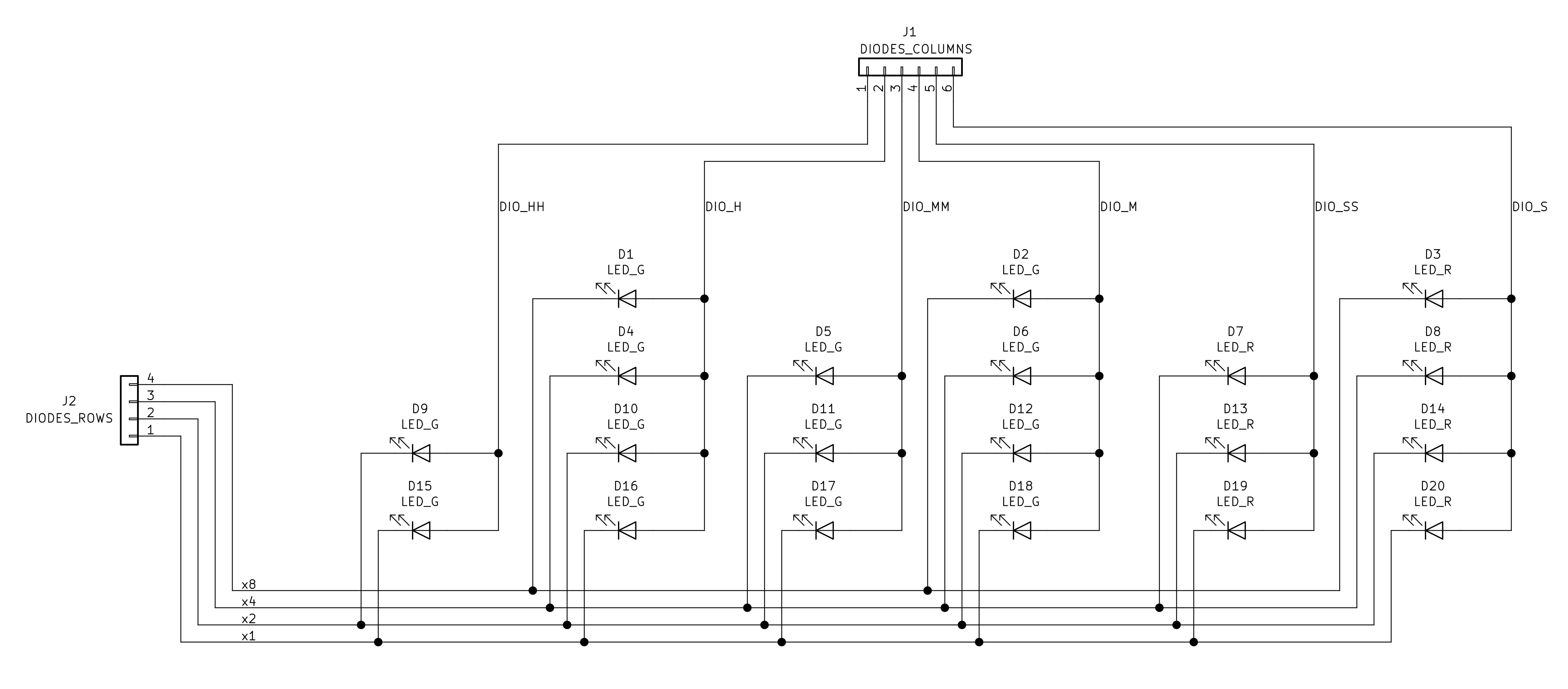
Everybody knows digital clocks, but only few people know binary clocks. In short, binary clocks show the numbers in binary format, 0 = LED off, 1 = LED on. In this case, we need at most 3 digits to represent numbers from 0 to 9. The first place is a multiplication of 8, the second place is a multiplication of 4, the third place is a multiplication of 2, and the fourth place is a multiplication of 1. For example, the number 5 is 0101 (0x8 + 1x4 + 0x2 + 1x1). In a clock, the numbers are limited to a certain range, for example the tens of hours can only be from 0 to 2 (0 - 24 hours), thus we can use just 2 LED diodes in the place of tens of hours. The same way we can use 3 diodes in the places of tens of minutes and tens of seconds (because their values will be from 0 to 5).
Circuit description
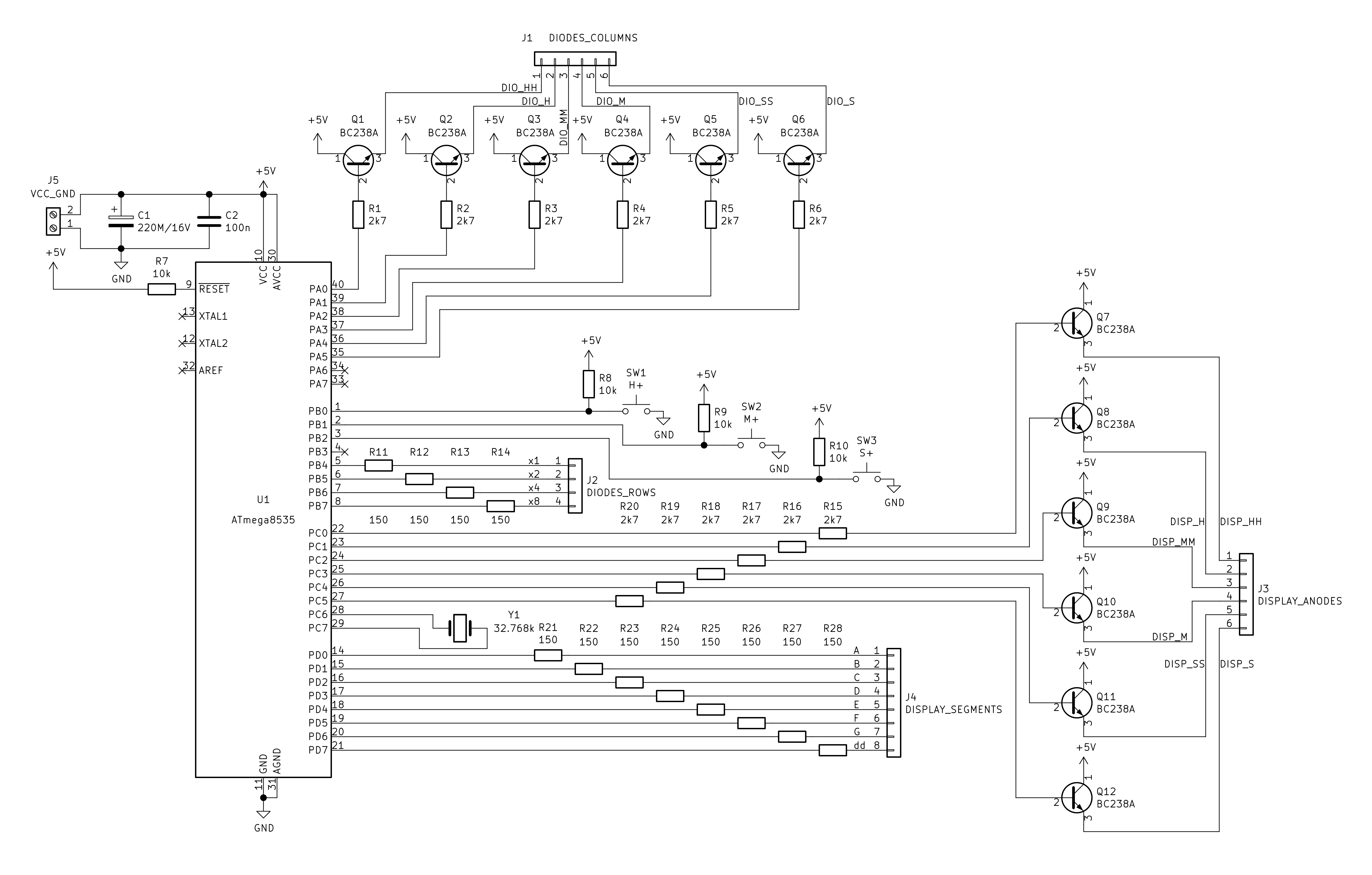
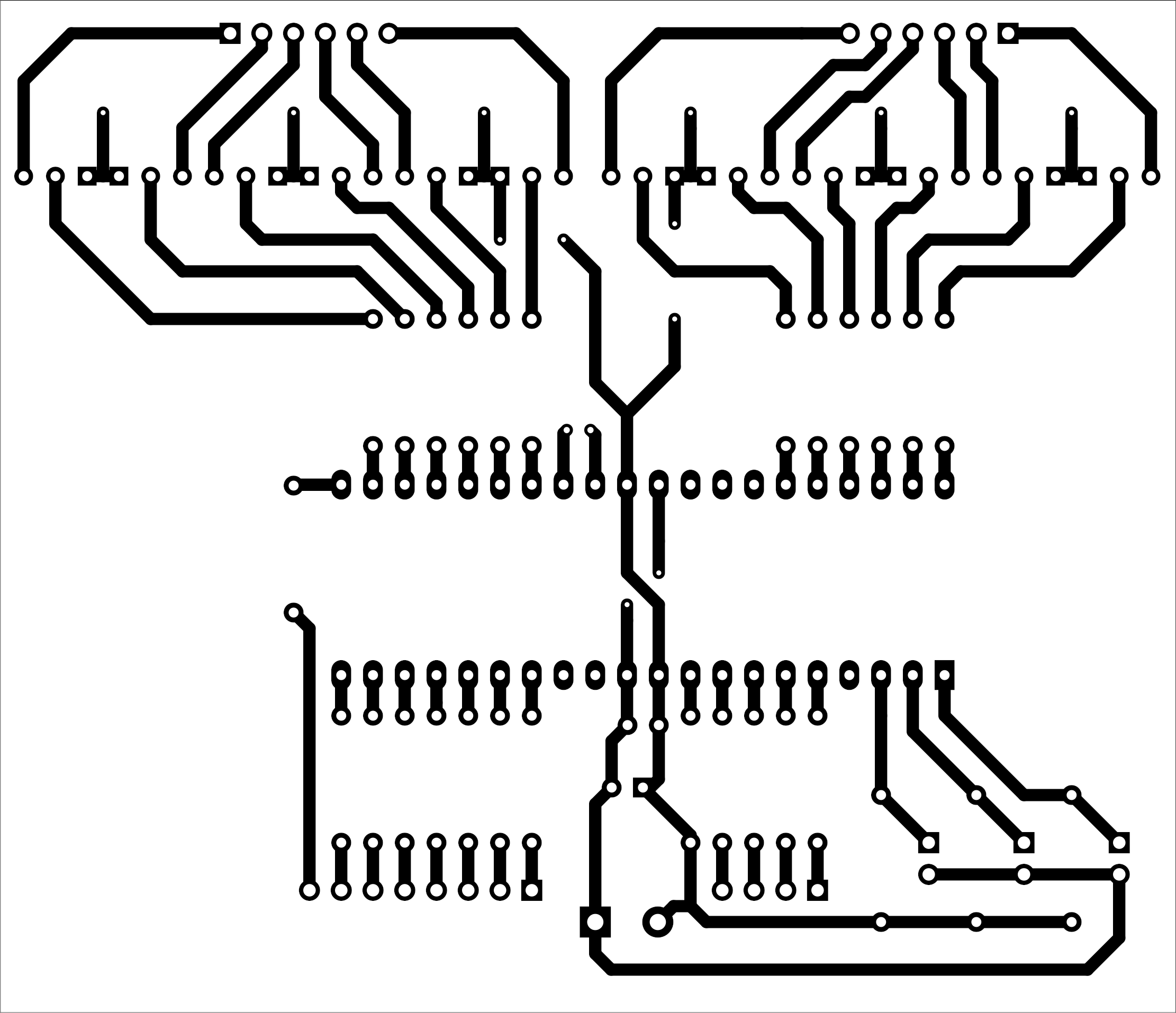
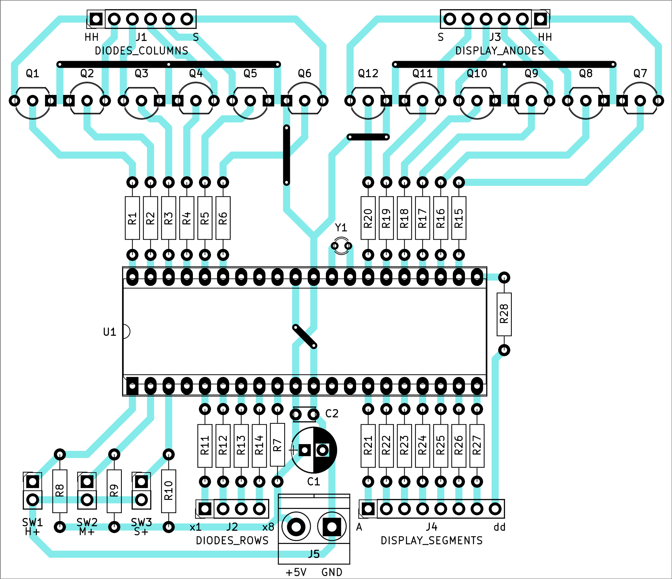
The schematic and PCB is below (click to enlarge). DPS dimensions are 94 x 81 mm and it is designed to fit into a plastic case type 1591USBK made by Hammond. The connection of LED diodes and display is shown separately, as these are not part of the PCB. All pictures are included in the archive that you can download at the bottom of this page.

The clock is powered by a 5 V supply from a wall adapter, so that we don't have to deal with mains voltage. Current consumption is around 70 mA, thus, at least a 100 mA adapter should suffice.
Supply voltage enters the pins of the ATmega8535 microcontroller, capacitors C1 and C2 are blocking. Three buttons are connected to the microcontroller, these are used to set up the clock - hours, minutes and seconds separately. When a button is pressed, the respective number is increased by 1, when a button is held, it increases faster.
As time base, a common 32.768 kHz crystal is used, that is often found in watches, PC mainboards and other consumer electronics. The accuracy of the clock depends on the crystal, but they are reasonably accurate.
The microcontroller (MCU for short) controls the display of time on LED diodes and LED display in a multiplex way. That means that not each LED or display segment is driven separately, but in digits for the display and in columns for the LEDs (the column that represents the digit). These are turned on so fast that human eye cannot recognize it, and it looks like everything is on at once.
Display segments and LED diodes are connected to the MCU via switching transistors. They make the LEDs and segments shine at the same brightness, regardless of how many are currently on. But what's also important, they reduce current supplied from the MCU pins that is limited by its manufacturer.
Construction
Six-digit displays are not readily available, so we can make our own by joining a 4- and a 2-digit display (of the same size and both with a common anode). To make it look more interesting, we can choose different color for each. Glue both together next to each one and then connect their pins such that they work in a multiplex mode - join all A-G pins, and solder cables to each segment and each digit (anode). I used a display of type AF-05643FG-B which also has a double dot between the second and the third digit so I used it as well. The double dot has its own anode (as if it was another digit) and its own cathode (the only segment in this "digit"). The anode of the double dot should be connected to the anode of the second digit. The cathode should be connected as display pin marked "dd" in the schematic. Pins marked „d“ should be left unconnected (decimal points are not used). The MCU program expect the double dot to be connected like this, but you can make your own. To illustrate it better, the connection of the display is depicted above, where common anodes are marked „CA“. Cut out a rectangular hole into the plastic enclosure for the display, but make sure it is only as wide and tall to make a tight fit with the display. Just to be sure, glue the display to the enclosure, but do not let the (super)glue run away on the front panel, because it will leave ugly white stains when dried.
LED diodes should be the same colors as the displays, these can be standard 5 mm diodes. Drill the holes not using a 5 mm drill, but a 4 mm one, and then carefully make the holes wide enough for the LEDs to fit tightly on their own. This approach avoids having to use glue. The diodes are also connected in multiplex, rows and columns separately. Bend their leads and solder them right at the back of the front panel - it's recommended to use new diodes that have long enough leads. Beware of any shorts between the rows and columns. A schematic of the LED connection is above, and a practical realisation is at the bottom of this page between the pictures.
Drill 3 holes from the top of the enclosure and mount the buttons there. Connect them to pins SW1, SW2 and SW3 on the PCB. Drill additional 2 holes on the back of the enclosure and mount the PCB there using screws and nuts.
The buttons, diodes and the display are connected to the PCB using standard 2.54 mm pin headers, it makes any repairs more comfortable. If you don't have any pin headers, you can just solder the wires to the PCB directly. Use a socket for the MCU and insert the MCU into the socket only after making sure that the supply voltage is present only on pins 10 (+5 V) and 11 (GND) and also 30 (+5 V) and 31 (GND) of the socket and that the current consumption without the MCU is 0 - if there is any, then check your PCB for unintentional shorts. The supply voltage is connected via a 5.08 mm screw terminal block. Don't forget to solder wire jumpers first (one is also under the MCU socket), and be careful about the polarity of the electrolytic capacitor.
Component values are not critical, you can use what you have at home, even some resistors of imprecise tolerance from dismantled electronics.
The program
MCU ATmega8535 has been chosen because of high number of pins and asynchronous mode support for TIMER2. This means that this timer is driven by an external crystal (32.768 kHz), instead of the MCU frequency. The MCU itself can be driven by its internal RC oscillator, as no high precision frequency is needed in this case. TIMER2 is set up with a prescaler of 128, because 32768/256 = 128 (256 is the maximum value of this 8-bitového timer). This makes sure that TIMER2 overflows one time per second. Interrupt service routine of this overflow is then simple, just the counter of seconds is increased (and if needed, also the minutes or hours). These numbers are stored in shared variables so that they can be read by the interrupt service routines of the other timers (TIMER0 a TIMER1), which control the multiplex display on the LED diodes and display. A detailed description of the timers can be found in the datasheet.
When programming the MCU, the fuses should be set like this: HIGH: 0xD9, LOW: 0x23.
The MCU software is included in the package for download below. It is commented enough, and will be useful if any changes or customizations are required.
Conclusion
The finished clock is on the picture below. This is just one of possible ways to make it look like, your creativity is limitless. Mine worked on the first try and is keeping time every day. The circuit can be also built on a breadboard where it works OK without problems.